Ion trap mobility spectrometer calibration method and system

a technology of mobility spectrometer and calibration method, which is applied in the direction of mass spectrometers, instruments, separation processes, etc., can solve the problems of no known accurate and easy-to-use calibration technique for ion trap mobility spectrometer, laborious analysis can take days to receive, and significant down time costs, etc., to achieve accurate and yet simple calibration method, and the effect of easy automation of the calibration method

Inactive Publication Date: 2008-04-17
GENERAL ELECTRIC CO
View PDF5 Cites 4 Cited by
  • Summary
  • Abstract
  • Description
  • Claims
  • Application Information

AI Technical Summary

Benefits of technology

[0008]In one aspect, the subject invention provides a more accurate and yet simple calibration method for an ion trap mobility spectrometer. The calibration metho...

Problems solved by technology

The results of the laboratory analysis, however, can take days to receive.
Meanwhile, the production line is idle resulting in significant down time costs.
Since the prior ion trap mobility spectrometers were typically used to detect the presence of narcotics or explosives, not their quantity, ther...

Method used


Image

  • Ion trap mobility spectrometer calibration method and system
  • Ion trap mobility spectrometer calibration method and system
  • Ion trap mobility spectrometer calibration method and system

Examples


Embodiment Construction

[0023]Aside from the preferred embodiment or embodiments disclosed below, this invention is capable of other embodiments and of being practiced or being carried out in various ways. Thus, it is to be understood that the invention is not limited in its application to the details of construction and the arrangements of components set forth in the following description or illustrated in the drawings. If only one embodiment is described herein, the claims hereof are not to be limited to that embodiment. Moreover, the claims hereof are not to be read restrictively unless there is clear and convincing evidence manifesting a certain exclusion, restriction, or disclaimer.

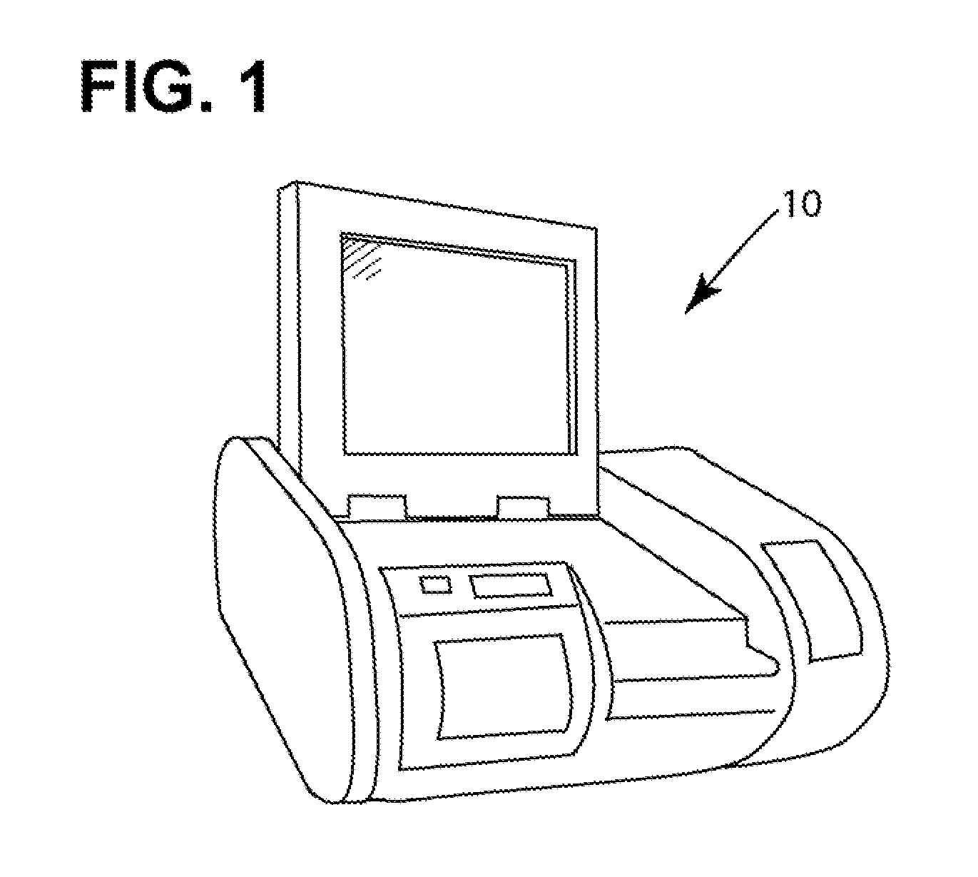
[0024]FIG. 1 depicts an ion trap mobility spectrometer instrument 10 (e.g., General Electric Corp.'s “Itemiser3” Dual Mode Detector). An operator swabs a surface of an item and inserts the swab into the instrument which then outputs an indication of whether a contraband is present.

[0025]As explained in the Background sectio...


PUM


Abstract

An ion trap mobility spectrometer calibration system and method wherein the maximum response of the spectrometer is determined. A quantity Q0 is chosen representing a response which is a predetermined percentage of the maximum response. Input to the ion trap mobility spectrometer are at least two known quantities Q1 and Q2 of an analyte, which have a predetermined relationship with Q0. The responses corresponding to R1 and R2 of the ion trap mobility spectrometer are observed based on the respective inputs of quantities Q1 and Q2. R1, R2, and Q1 and Q2 are then used to calculate the calibration constants in an equation describing a curve where the response of the ion trap mobility spectrometer is a function of the quantity of the analyte input therein. The calculated calibration constants are input to thereafter determine, from the response, the quantity of a detected analyte based on the equation.

Description

FIELD OF THE INVENTION[0001]The subject invention relates to the calibration of analytical instruments.BACKGROUND OF THE INVENTION[0002]In the pharmaceutical industry, cleanliness of the drug manufacturing devices and equipment is a concern. Between batches, the Federal Food and Drug Administration (FDA) requires that the equipment used be cleaned to prevent cross-contamination. The cleaning effort must be validated and the analysis used must be accurate to within 15%. It is known to swab the equipment and send the swab to a laboratory for analysis. There, it is common to use a high pressure liquid chromatography (HPLC) system or total organic carbon (TOC), among other techniques, to analyze the swab for contaminants.[0003]The results of the laboratory analysis, however, can take days to receive. Meanwhile, the production line is idle resulting in significant down time costs.[0004]Accordingly, there has been an interest in utilizing smaller portable analyzers which could be located ...

Claims


Application Information

Patent Timeline
IPC IPC(8): H01J49/00
CPCG01N35/00693H01J49/42H01J49/0009
Inventor LI, XUE-SONG SCOTT
Owner GENERAL ELECTRIC CO
Why Eureka
Try Eureka