Suspension System

a suspension system and suspension technology, applied in the direction of resilient suspensions, interconnection systems, vehicle components, etc., can solve the problems of vehicle overturning, vehicle overturning, and frame tilting, so as to reduce vibration, reduce the impact on the overall structure of the vehicle, and increase the life of load-bearing pads

Active Publication Date: 2008-04-17
DEERE & CO
View PDF14 Cites 14 Cited by
  • Summary
  • Abstract
  • Description
  • Claims
  • Application Information

AI Technical Summary

Benefits of technology

[0023] The suspension system according to the invention constitutes a suspension with hydraulic roll stabilization for the sprung axle of the vehicle. It is advantageous here that the sprung axle can be sprung without the need for additional mechanical measures for roll stabilization. The aforementioned suspension system has two hydraulic cylinders, which can be operated independently of one another and which resiliently support the frame of the vehicle in relation to the axles of the vehicle. In order to prevent rolling movements occurring whilst underway, the hydraulic cylinders are connected to one another in a hydraulic cross connection. The associated compensating movements of the one hydraulic cylinder during movements of the other hydraulic cylinder counteract rolling of the frame relative to the vehicle axes, so that rolling movements of the vehicle are hydraulically suppressed. A sprung axle considerably reduces the impacts on the overall structure of the vehicle and thus increases the life of load-bearing pads. Owing to the reduced vibrations, even smaller components are less stressed, so that their reliability is increased. The suspension system furthermore brings considerable improvements in ride comfort and increases the driving stability at high speeds. This may also afford time advantages in the operation of the vehicle. A further advantage is that the suspension system according to the invention manages with two hydraulic accumulators, provided that it is ensured that suspension movements cannot lead to a vacuum in the hydraulic accumulators, which except in piston accumulators would lead to damaging of the hydraulic accumulator.

Problems solved by technology

Whereas with the suspension deactivated the vehicle is stable, on activation of the suspension the support width of the vehicle is reduced, with the result that forces may be introduced, which can cause the vehicle to overturn.
Such a tipping movement would occur very rapidly on sudden activation of the suspension and in an extreme case would lead to overturning of the entire vehicle.
Detecting this pressure change is not without problems, since a constrained pressure may be present in the hydraulic cylinder, which has resulted due to external heating or an adjustment of the hydraulic cylinder, for example.
In this case a negative force means that the frame does not rest on the cylinder rod, but instead is pulling on it, which when the rod-side switch valve opens could lead to an extending of the piston rod of the hydraulic cylinder and hence to a tilting of the frame.

Method used


Image

  • Suspension System
  • Suspension System
  • Suspension System

Examples


Embodiment Construction

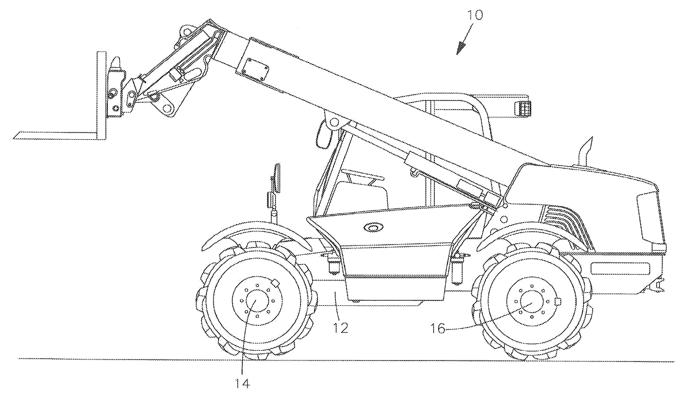
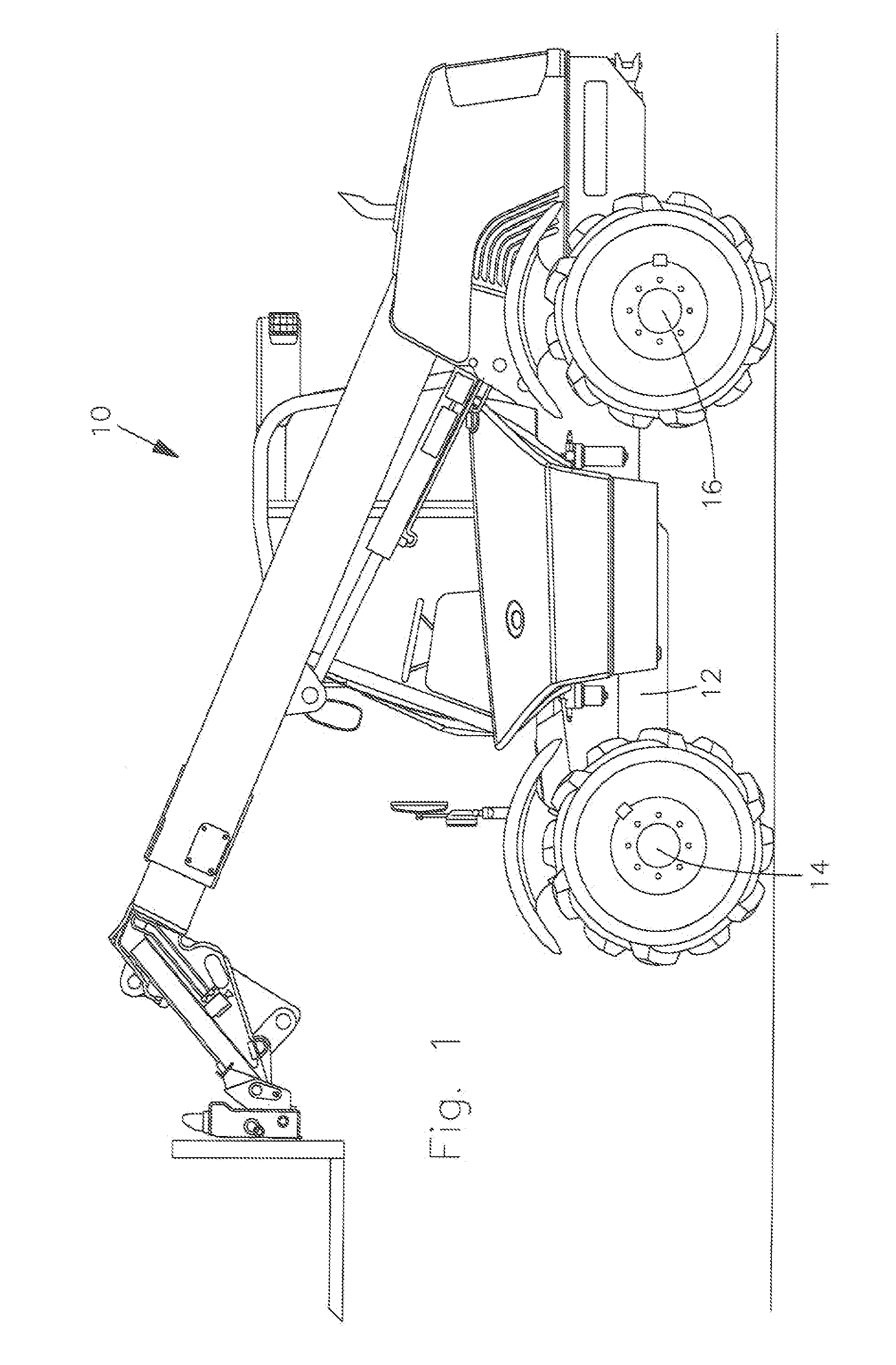
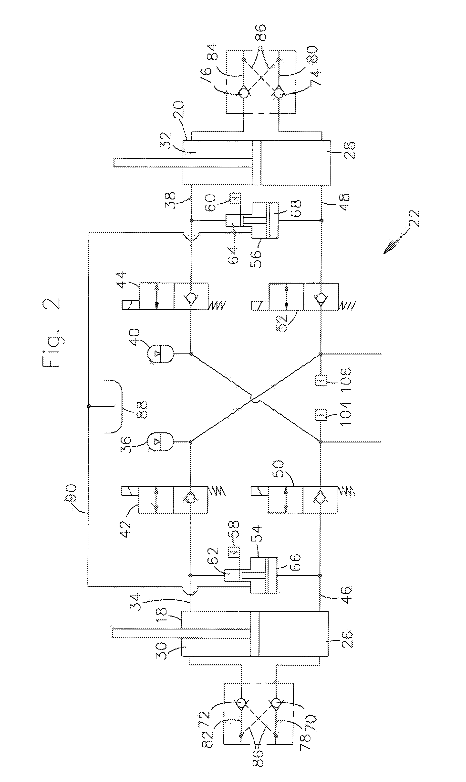
[0033]FIG. 1 shows an agricultural vehicle 10 in the form of a telescopic loader, which has a frame 12, a font axle 14 and a rear axle 16. The rear axle 16 is floating, as is usual for telescopic loaders. The front axle 14 is sprung in such a way that hydraulic cylinders 18, 20, which are part of a suspension system 22 with hydraulic roll stabilization, explained in more detail in FIGS. 2 to 6, extend between the frame 12 and the front axle 14, on either side of the vehicle central longitudinal axis. Similarly, the front axle 12 could also be floating and the hydraulic cylinder for suspension of the rear axle 16 could be correspondingly arranged between the rear axle 16 and the frame 12. It is also feasible to use such a suspension system 22 on a tractor (with or without front loader), a wheeled loader or another loader vehicle.

[0034] The suspension system 22 will be described in detail with reference to FIGS. 2 to 6, the system components for the load state sensing being represent...


PUM


Abstract

A suspension system for an agricultural or construction industry vehicle is described. The suspension system comprises two hydraulic cylinders which support a frame in relation to an axle of the vehicle, the hydraulic cylinders being hydraulically connected to one another in a cross connection, so that a piston-side chamber of the one hydraulic cylinder is connected to the piston rod-side chamber of the other hydraulic cylinder and vice versa, in each case one hydraulic accumulator assigned to a hydraulic cylinder, a hydraulic source, a hydraulic tank, a control valve device, an electronic control init, electrically switchable switch valves which are arranged in the cross connection between the hydraulic accumulators and the hydraulic cylinders, and a first and second supply line, which supply lines connect the control vale device to the cross connection. In order to prevent the activation of a suspension state in critical vehicle states, means for the detection and compensation of load states of the vehicle are provided in the suspension system.

Description

FIELD OF THE INVENTION [0001] The invention relates to a suspension system for an agricultural or construction vehicle. More particularly the invention relates to suspension system for a loader vehicle. BACKGROUND OF THE INVENTION [0002] Suspension systems in which the front axle is hydro-pneumatically sprung are known in agricultural vehicles, such as tractors. Front axle suspension affords the driver greater ride comfort and increased working efficiency, since both the speed of travel and the traction of the vehicles can be significantly increased compared to unsprung vehicles. The hydraulic design configuration of such a front axle suspension generally comprises hydraulic accumulators, which are connected to hydraulic cylinders arranged on the front axle, which in turn connect a vehicle frame to the front axle. In such vehicles the front axle is embodied as a fully floating axle, so as to provide a sprung suspension. Such vehicles furthermore have a rigid rear axle, in order to c...

Claims


Application Information

Patent Timeline
Patent Type & Authority Applications(United States)
IPC IPC(8): B60G21/06
CPCB60G17/005B60G17/056B60G21/073B60G2800/9124B60G2400/60B60G2500/02B60G2800/012B60G2300/083
Inventor BITTER, MARCUS
Owner DEERE & CO
Why Eureka
Try Eureka