Catalyst support structure

a support structure and catalyst technology, applied in the field of exhaust systems, can solve the problems of unnecessarily high assembly man-hours, high parts count, and high assembly man-hours, and achieve the effects of unnecessarily high total cost, high parts count, and disclosed cost and complexity of catalyst assembly

Active Publication Date: 2008-04-17
YAMAHA MOTOR CO LTD
View PDF4 Cites 0 Cited by
  • Summary
  • Abstract
  • Description
  • Claims
  • Application Information

AI Technical Summary

Benefits of technology

[0007] An aspect of at least one of the embodiments disclosed herein includes the realization that the cost and complexity of the catalyst assembly disclosed in Japanese Patent Document JP-A-Hei 3-157139 can be reduced. For example, in the catalyst device of Japanese Patent Document JP-A-Hei 3-157139 the honeycomb structure and the outer pipe are assembled together via an intermediate pipe. This results in a high parts count and requires multiple brazing steps. As a result, the man-hours required for assembly and total cost are unnecessarily high. In a

Problems solved by technology

This results in a high parts count and requires multiple brazing steps.
As a result, the man-hours required for assembly and total cost are unnecessarily high.
Thus, if a significan

Method used


Image

  • Catalyst support structure
  • Catalyst support structure
  • Catalyst support structure

Examples


Embodiment Construction

[0024] Improved exhaust systems for an engine are disclosed herein. Although the present exhaust systems are illustrated and described in the context of an engine of a personal watercraft, certain aspects of the present inventions can be used with engines of other types of vehicles, as well as with other types of prime movers.

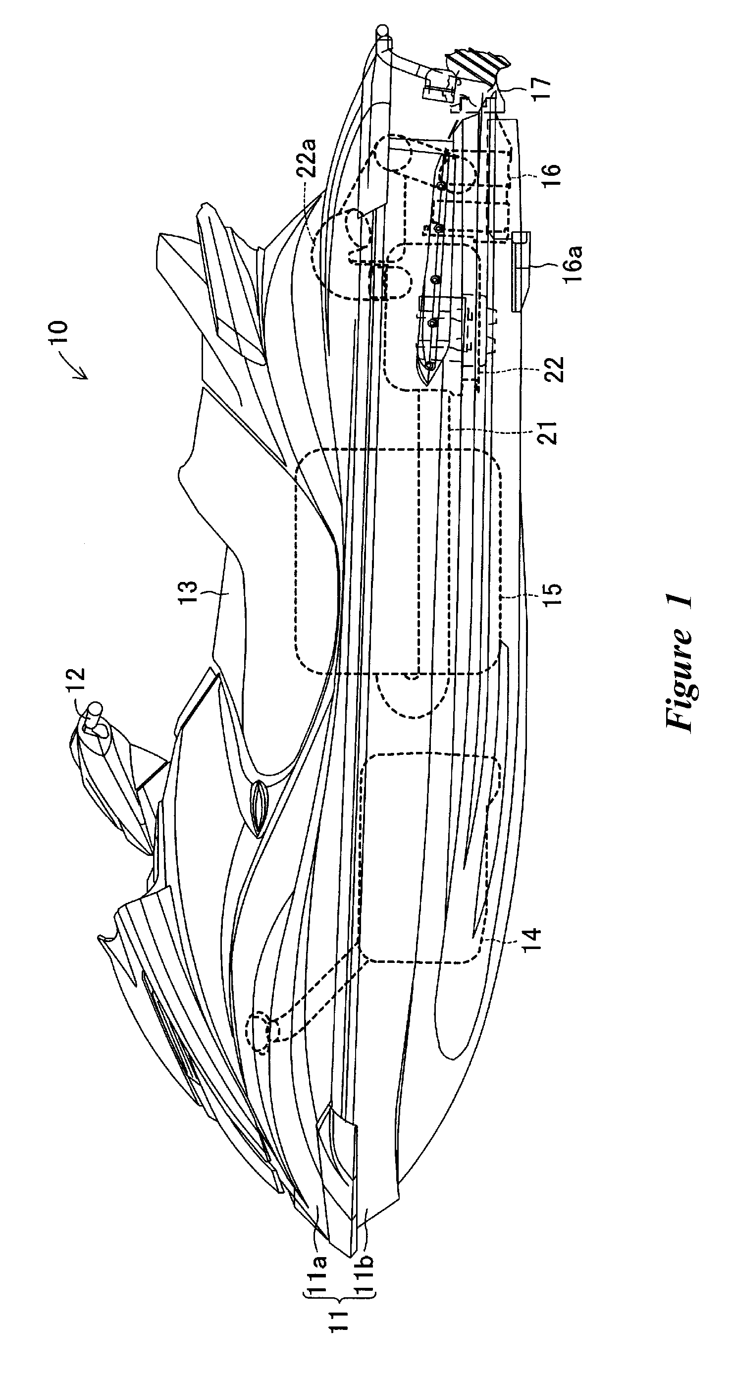
[0025]FIG. 1 illustrates a water vehicle 10 having a catalyst support structure A (see FIG. 4) in accordance with an embodiment. The water vehicle 10 can have a body 11 including a deck 11a and a hull 11b. The body 11 can have steering handlebars 12 disposed on the upper part of the body 11 and slightly in front of its center.

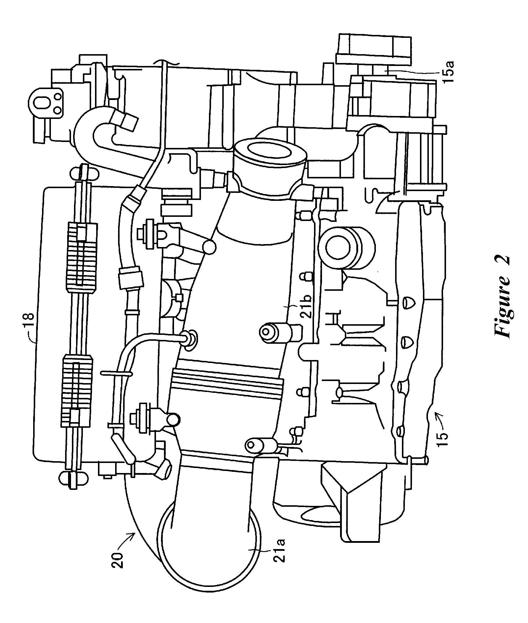
[0026] A seat 13 can be disposed centrally of the upper part of the body 11. A fuel tank 14 for holding fuel therein can be disposed at the front bottom inside the body 11. An engine 15 can be disposed at the center bottom inside the body 11.

[0027] A propulsion unit 16 can be disposed centrally in the width direction of the body 11 at t...


PUM


Abstract

A catalyst for purifying an exhaust gas can include a carrier having a honeycomb structure, an outer pipe for covering a part of the carrier, and a brazing foil for joining the outer peripheral surface of the carrier and the inner peripheral surface of the outer pipe on the downstream side of the catalyst. The catalyst can be fixed to a support flange such that an axial direction of the catalyst coincides with the direction in which an exhaust gas flows through an exhaust pipe. An upstream end of the brazing foil can be aligned with the upstream end of a catalyst fixing part of the support flange. An upstream end of the catalyst fixing part can be positioned upstream of the axial middle of the carrier. The brazing foil can be provided in a portion from the upstream end of the catalyst fixing part to the downstream side of the carrier. The catalyst can be supported at its generally middle part by the support flange. An upstream end of the outer pipe can be aligned with the upstream end of the catalyst fixing part.

Description

PRIORITY INFORMATION [0001] This application is based on and claims priority to Japanese Patent Application No. 2006-218855, filed Aug. 10, 2006, the entire contents of which is hereby expressly incorporated by reference. BACKGROUND OF THE INVENTIONS [0002] 1. Field of the Inventions [0003] The preset inventions relate to exhausts systems, and more particularly, to a catalyst support structure for supporting a catalyst installed in an exhaust pipe. [0004] 2. Description of the Related Art [0005] Conventional engines of small watercrafts, such as personal watercraft and other vehicles typically include exhaust pipes for guiding exhaust gasses to the atmosphere. Some of the exhaust systems of these vehicles include a catalyst for purifying the exhaust gas before it is discharged into the atmosphere. [0006] For example, Japanese Patent Document JP-A-Hei 3-157139 discloses a catalyst (metal carrier for exhaust gas purification) formed by a honeycomb structure wound into a roll with an o...

Claims


Application Information

Patent Timeline
IPC IPC(8): B01D53/94F01N3/035B01D53/86F01N3/02F01N3/28F01N13/12
CPCF01N13/004F01N3/2875
Inventor KINOMOTO, NAOKIYAMAZAKI, SUSUMU
Owner YAMAHA MOTOR CO LTD
Why Eureka
Try Eureka