Electrified ceiling framework underside connectors

a technology of underside connectors and cables, applied in the direction of flexible/turnable line connectors, ceilings, coupling device connections, etc., can solve the problems of difficult service or reconfiguration, inability to service or reconfigure, and the fraction of devices found in those buildings to operate on low voltage direct current. , to achieve the effect of improving the physical and/or electrical conta

Inactive Publication Date: 2008-04-17
ARMSTRONG WORLD INDUSTRIES
View PDF18 Cites 72 Cited by
  • Summary
  • Abstract
  • Description
  • Claims
  • Application Information

AI Technical Summary

Benefits of technology

[0011]An advantage of the electrical connectors of the present invention is the suitable electrical contact achieved via rotation of the connector. Mechanical bias of the connector may be utilized to further improve the physical and / or electrical contact.
[0012]Another advantage of the electrical connector of the present invention is the removal and / or penetration of dust, dirt and / or oxide that may be present on electrical conductors to be contacted.
[0013]Still another advantage of the electrical connector of the present invention is the flexibility in locating the positive and negative polarity conductive surfaces in order to allow connection to a greater variety of low voltage devices.
[0014]Still another advantage of the electrical connector of the present invention is that connector may support the weight of electrical devices via a mechanical interlock with a ceiling support member.

Problems solved by technology

Yet, an increasing fraction of devices found in those buildings actually operate on low voltage direct current (DC).
Installation of devices utilizing low voltage DC has been typically limited to locations in which a pair of wires is routed from the voltage source.
The grid framework and ceiling tile system may provide a visual barrier between the living or working space and the infrastructure systems mounted overhead.
These known systems suffer from the drawback that the complex network of wires occupy the limited space above the ceiling grid, and are difficult to service or reconfigure.
These tracks have the drawbacks that they typically require wiring and mechanical support from the plenum space above the ceiling grid framework.
In addition, the track systems are typically viewable from the room space and are aesthetically undesirable.
Further still, known track systems typically utilize higher voltage AC power and connect to AC powered devices, requiring specialized installation and maintenance.

Method used


Image

  • Electrified ceiling framework underside connectors
  • Electrified ceiling framework underside connectors
  • Electrified ceiling framework underside connectors

Examples


Embodiment Construction

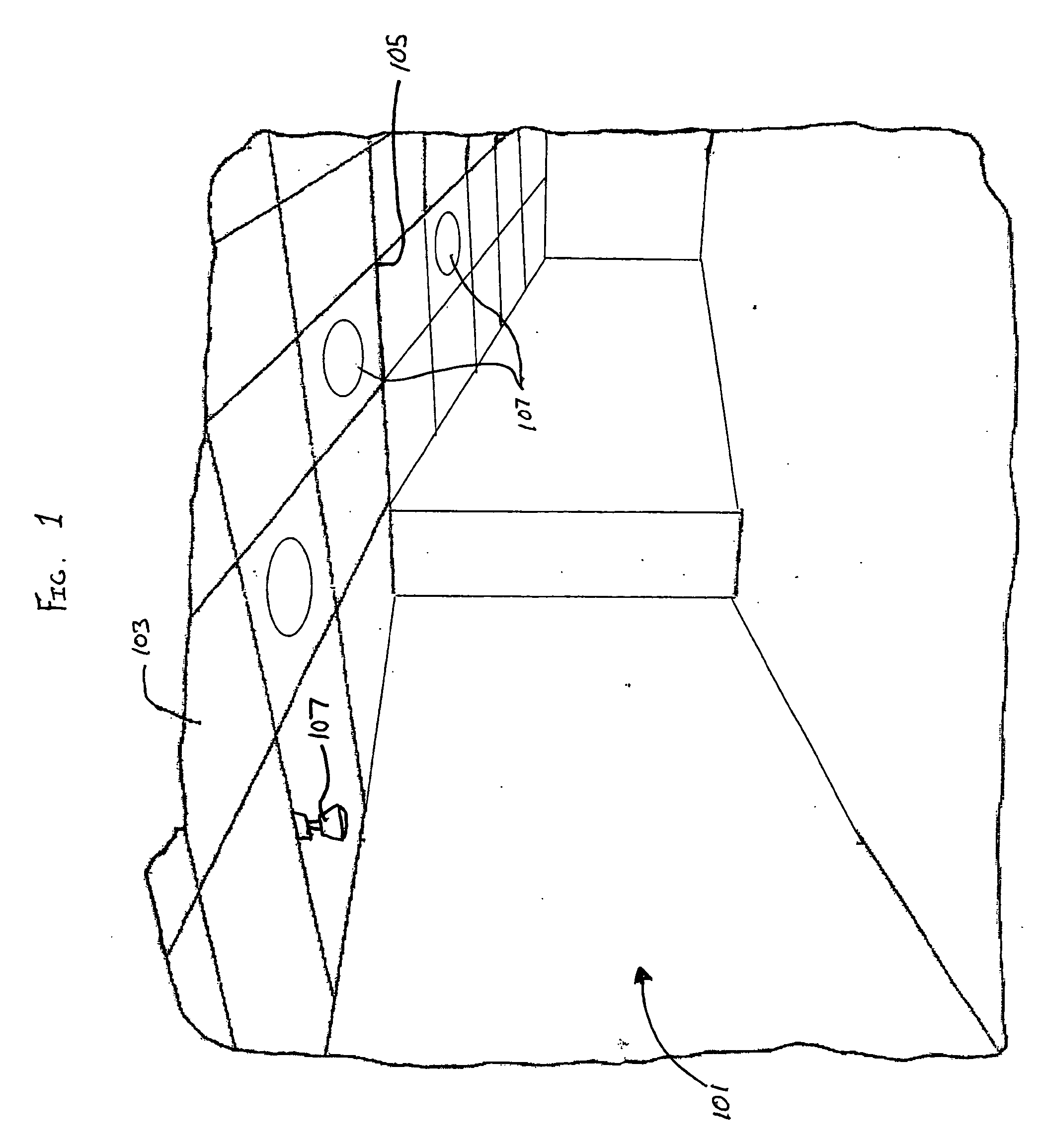
[0029]The present invention includes connectors for use with an electrified ceiling. FIG. 1 shows a room space 101 having a ceiling 103 supported by a ceiling grid framework 105. The ceiling 103 may include decorative tiles, acoustical tiles, insulative tiles, lights, heating ventilation and air conditioning (HVAC) vents, other ceiling elements or covers and combinations thereof. Low voltage devices 107, such as light emitting diode (LED) lights, speakers, smoke or carbon monoxide detectors, wireless access points, still or video cameras, or other low voltage devices, may be utilized with the electrified ceiling. Power for the low voltage devices 107 is provided by conductors 201 (see FIG. 2) placed upon ceiling grid framework 105.

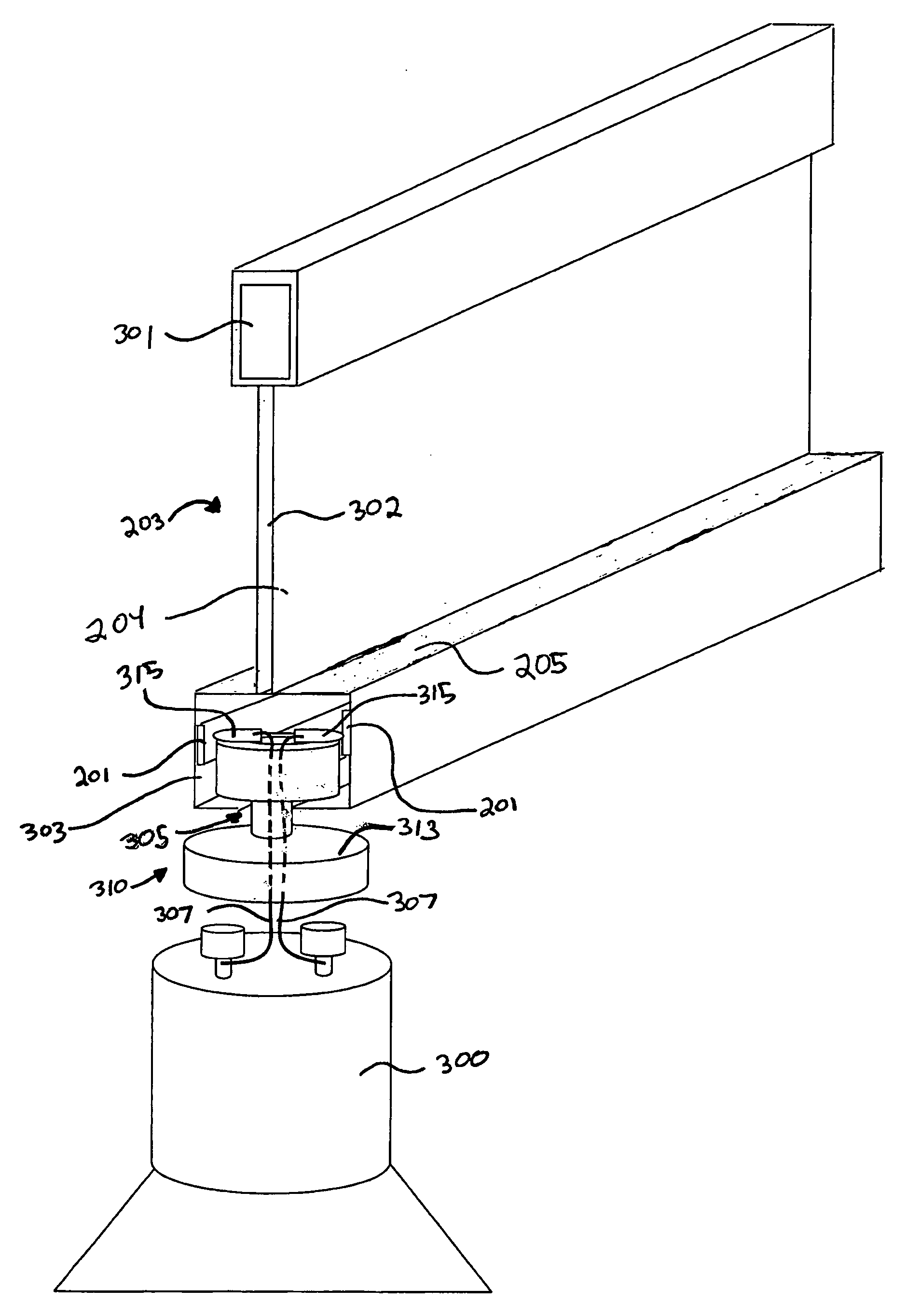
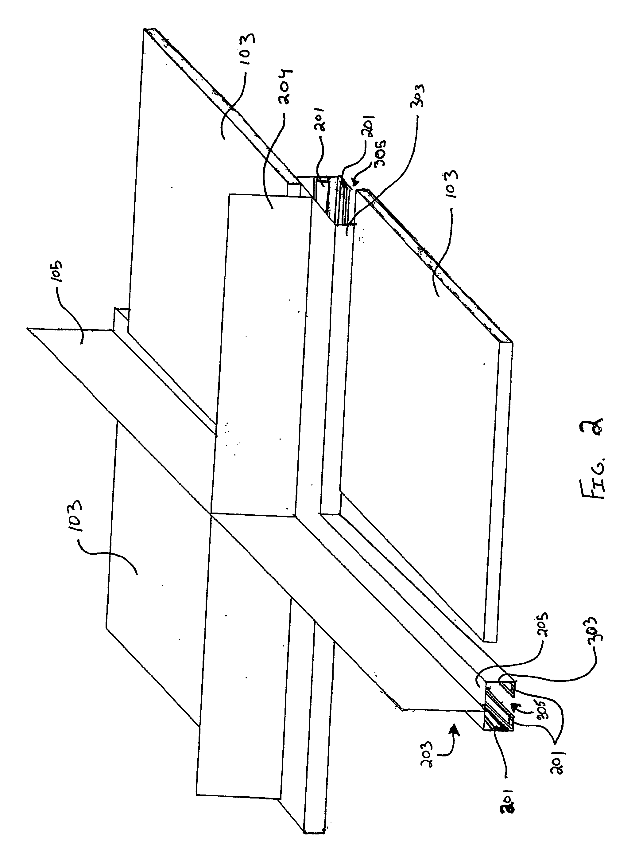
[0030]FIG. 2 shows a perspective view of a segment of the ceiling grid framework 105 viewed from above with a portion of the ceiling 103 removed. The ceiling grid framework 105 includes intersecting support members 203 having a lower box 303. Lower box 303...


PUM


Abstract

An electrical connector for connecting low voltage device to an electrified ceiling framework. The connector includes a connector body and a conductive member attached to the connector body. The conductive member includes a contact portion configured to provide electrical contact to a conductive surface of the electrified ceiling framework. The connector is also configurable in a first position and a second position. The first position permits insertion of a portion of the connector into an opening in the electrified ceiling framework. The second position engages the electrified ceiling framework to provide an electrical connection and mechanical support to the connector and devices that may be attached thereto.

Description

FIELD OF THE INVENTION[0001]The present invention is directed to connectors for making electrical connections between conductive elements and specifically for providing electrical connections to devices connectable from below a ceiling grid framework.BACKGROUND OF THE INVENTION[0002]The electrical grid connecting America's power plants, transmission lines and substations to homes, businesses and factories operate almost entirely within the realm of high voltage alternating current (AC). Yet, an increasing fraction of devices found in those buildings actually operate on low voltage direct current (DC). Those devices include, but are not limited to, digital displays, remote controls, touch-sensitive controls, transmitters, receivers, timers, light emitting diodes (LEDs), audio amplifiers, microprocessors, and virtually all products utilizing rechargeable batteries.[0003]Installation of devices utilizing low voltage DC has been typically limited to locations in which a pair of wires is...

Claims


Application Information

Patent Timeline
Patent Type & Authority Applications(United States)
IPC IPC(8): H01R25/00
CPCH01R35/04H01R25/142E04B9/006E04B9/064
Inventor PATTERSON, BRIAN T.MANNING, RANDY MARSHALLMYERS, JERE W.FRECSKA, SANDOR
Owner ARMSTRONG WORLD INDUSTRIES
Why Eureka
Try Eureka