Fuel supply apparatus and fuel supply control apparatus for internal-combustion engine

Inactive Publication Date: 2008-04-24
DENSO CORP
View PDF6 Cites 28 Cited by
  • Summary
  • Abstract
  • Description
  • Claims
  • Application Information

AI Technical Summary

Benefits of technology

[0013]The present invention addresses the above disadvantages. Thus, it is an objective of the present invention to supply a plurality of fuels to an injector of an internal-combustion engine using a simple configu

Problems solved by technology

Reduction in environment pollution caused by exhaust gas, and a response to resource depletion are formidable challenges to a current transportation system led by automobiles.
However, mixed fuel including alcohol has poor ignition performance as compared to gasoline fuel, thereby deteriorating starting performance at low temperature or in a cold region.
Furthermore, since alcohol is more easily vaporized than gasoline fuel, alcohol is vaporized in a fuel flow passage in an injection valve at the high-temperature restarting, so that a vapor lock may be caused.
However, the device in JP61-11445A requires the two systems of fuel supply passages and pumps, which results in its complex configuration.
As a result, fuel with its alcohol component separated cannot be promptly injected fro

Method used


Image

  • Fuel supply apparatus and fuel supply control apparatus for internal-combustion engine
  • Fuel supply apparatus and fuel supply control apparatus for internal-combustion engine
  • Fuel supply apparatus and fuel supply control apparatus for internal-combustion engine

Examples


first embodiment

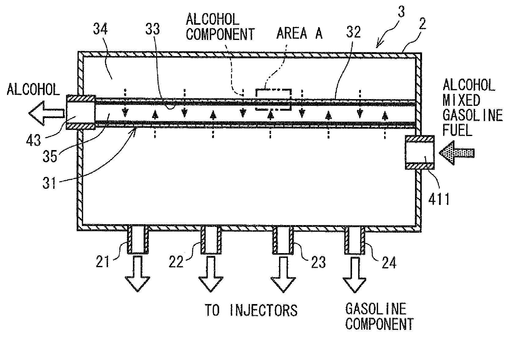
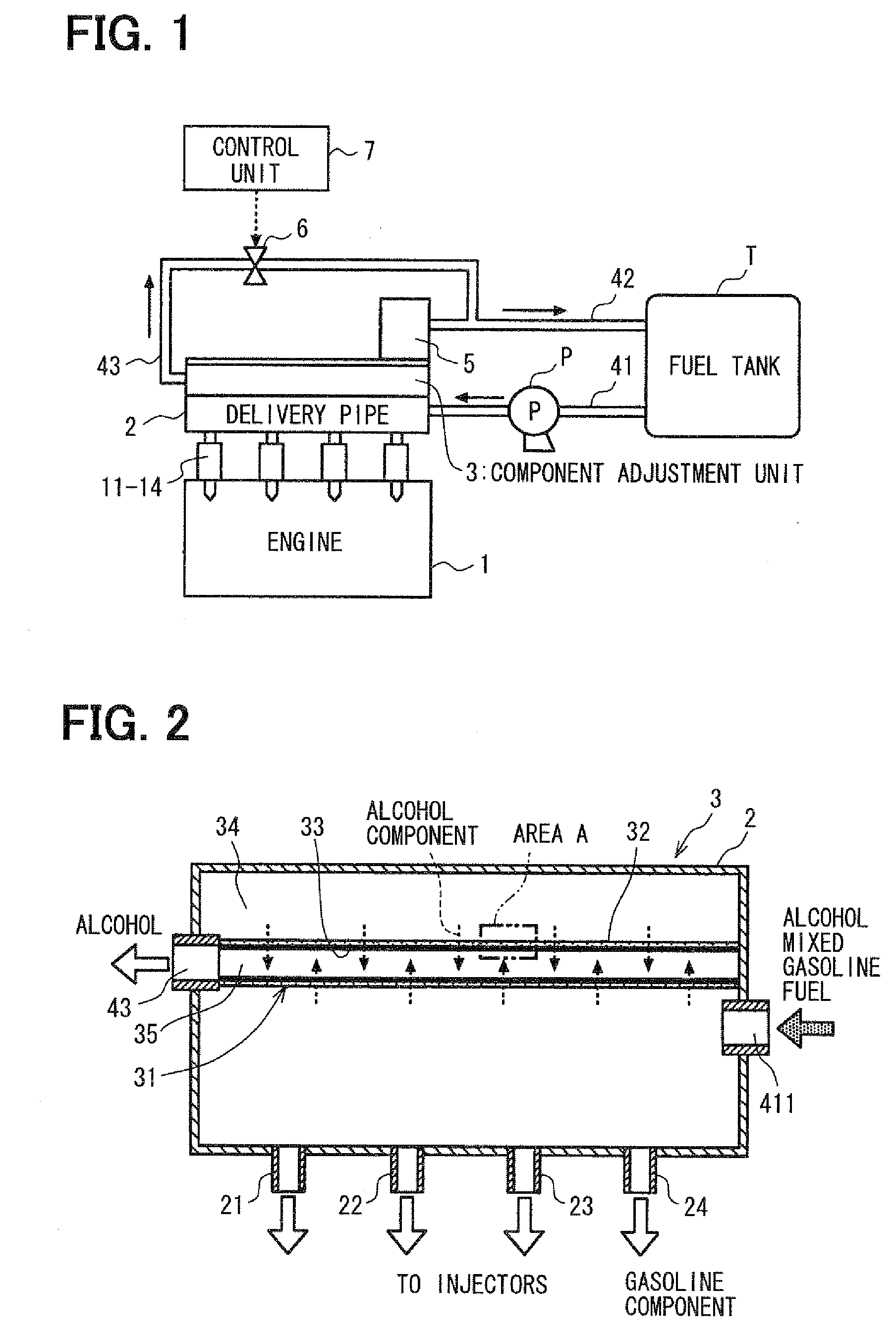
[0040]In the first embodiment, by providing the component adjustment unit 3 in the delivery pipe 2 on an immediate upstream side of the injectors 11 to 14, fuel having more gasoline components is supplied at the starting of the engine 1. As a result, the ignition performance is improved, and thus the startability is greatly improved. By dividing the delivery pipe 2 with the component separation wall 31, the component adjustment unit 3 is easily provided. Additionally, an installation space does not need to be newly created for the component adjustment unit 3, and the component adjustment unit 3 is on an immediate upstream side of the injectors 11 to 14. Consequently, fuel with its component adjusted is promptly and evenly supplied. Since a little fuel, that is, several cubic centimeters (cc) of fuel or less, is normally used at the starting, by providing the component adjustment unit 3 in the fuel supply passage near the injectors 11 to 14 to separate the alcohol component while the...

second embodiment

[0041]The component adjustment unit 3 is not necessarily disposed in the delivery pipe 2. When the component adjustment unit 3 is disposed closer to the injectors 11 to 14, less alcohol components are separated to increase the concentration of the gasoline component. the present invention is shown in FIG. 6. As shown in FIG. 6, each component adjustment unit 3 is disposed halfway along a corresponding one of the outlet pipes 21 to 24 connecting the delivery pipe 2 and the injectors 11 to 14, respectively.

[0042]FIG. 7 is a schematic view showing a configuration of a component adjustment unit 3 of the second embodiment. In FIG. 7, as an example, the component adjustment unit 3 disposed between the injector 11 and the outlet pipe 21 is shown. The component adjustment unit 3 includes a container structure 36 and a component separation wall 31. The container structure 36 serves as an individual fuel supply chamber, and the component separation wall 31 is disposed in the container structu...

third embodiment

[0047]As shown in FIG. 8, the decompression pump P1 is disposed between an electromagnetic valve 6 and the delivery pipe 2, and is controlled to operate by a control unit 7. In the third embodiment, when the engine 1 is stopped, the electromagnetic valve 6 is opened and the decompression pump P1 is actuated to start the separation of the alcohol component. By making pressure in the posterior chamber 35 even lower, the pressure difference between the anterior chamber 34 and the posterior chamber 35 becomes great. As a result, since a speed of the separation of the alcohol component increases, the separation of the alcohol component is promoted even in the configuration whereby the component adjustment unit 3 is disposed in a delivery pipe 2 having large volume. Thus, fuel with high ignition performance is immediately supplied to the injectors 11 to 14 at the starting of the engine 1, thereby improving starting performance-enhancing effects.

[0048]In addition, the decompression pump P1...


PUM

PropertyMeasurementUnit
Pressureaaaaaaaaaa
Speedaaaaaaaaaa

Abstract

A fuel supply apparatus includes a component adjustment unit, a low-pressure side passage, and a valve. The unit adjusts component composition of fuel by separating a particular component from fuel. The unit includes a component separation wall, which divides an interior of a portion of a fuel supply passage between an anterior chamber and a posterior chamber. The wall includes a separation membrane, which the particular component of fuel in the anterior chamber selectively permeates to be separated. The particular component after passing through the wall is temporarily stored in the posterior chamber. When the low-pressure side passage connected to the posterior chamber is opened by the valve, the particular component is separated. Fuel, from which the particular component is separated, is supplied to an injection valve from the anterior chamber. When the low-pressure side passage is closed by the valve, the separation of the particular component is restricted.

Description

CROSS REFERENCE TO RELATED APPLICATION[0001]This application is based on and incorporates herein by reference Japanese Patent Application No. 2006-287584 filed on Oct. 23, 2006.BACKGROUND OF THE INVENTION[0002]1. Field of the Invention[0003]The present invention relates to a fuel supply apparatus and a fuel supply control apparatus for an internal-combustion engine.[0004]2. Description of Related Art[0005]Reduction in environment pollution caused by exhaust gas, and a response to resource depletion are formidable challenges to a current transportation system led by automobiles. Development of alternative fuel to conventional hydrocarbon fuel, and improvement of gasoline and light oil fuel are under consideration as alternative fuels to automotive fuel. The improved gasoline and light oil fuel can be employed in an existing engine without modification, which is advantageous on the cost front. For example, mixed fuel as a result of mixing inexpensive alcohol into gasoline, and fuel as...

Claims


Application Information

Patent Timeline
IPC IPC(8): F02M57/00B01D63/00
CPCB01D61/027B01D71/028F02M43/00F02M2200/9046F02M69/54F02M2200/90F02M69/465
Inventor ARAKAWA, MIYAONISHIJIMA, YOSHIAKIKUROYANAGI, MASATOSHIKIYOZUMI, YOSHIMICHI
Owner DENSO CORP
Why Eureka
Try Eureka