Rotary electric machine, crank-shaped continuously winding coil, distribution winding stator and forming method thereof

a technology stators, which is applied in the direction of windings, dynamo-electric components, synchronous machines, etc., can solve the problems of miniaturization achieve the effects of high efficiency of rotary electric machines, excellent rotary characteristics, and high power outpu

Active Publication Date: 2008-04-24
HITACHI LTD
View PDF9 Cites 60 Cited by
  • Summary
  • Abstract
  • Description
  • Claims
  • Application Information

AI Technical Summary

Benefits of technology

[0018]By the present invention, the distribution winding stator using the coil which winds a conductor of the rectangular cross section by a lap winding is structured such that the coil end is made smaller than before, and the conductor is split and disposed in the

Problems solved by technology

With respect to the miniaturization, since the size of the stator core is fixed, making the coil ends of the stator core both end

Method used


Image

  • Rotary electric machine, crank-shaped continuously winding coil, distribution winding stator and forming method thereof
  • Rotary electric machine, crank-shaped continuously winding coil, distribution winding stator and forming method thereof
  • Rotary electric machine, crank-shaped continuously winding coil, distribution winding stator and forming method thereof

Examples


first embodiment

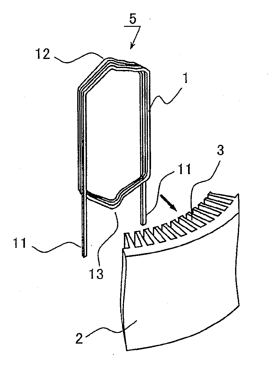
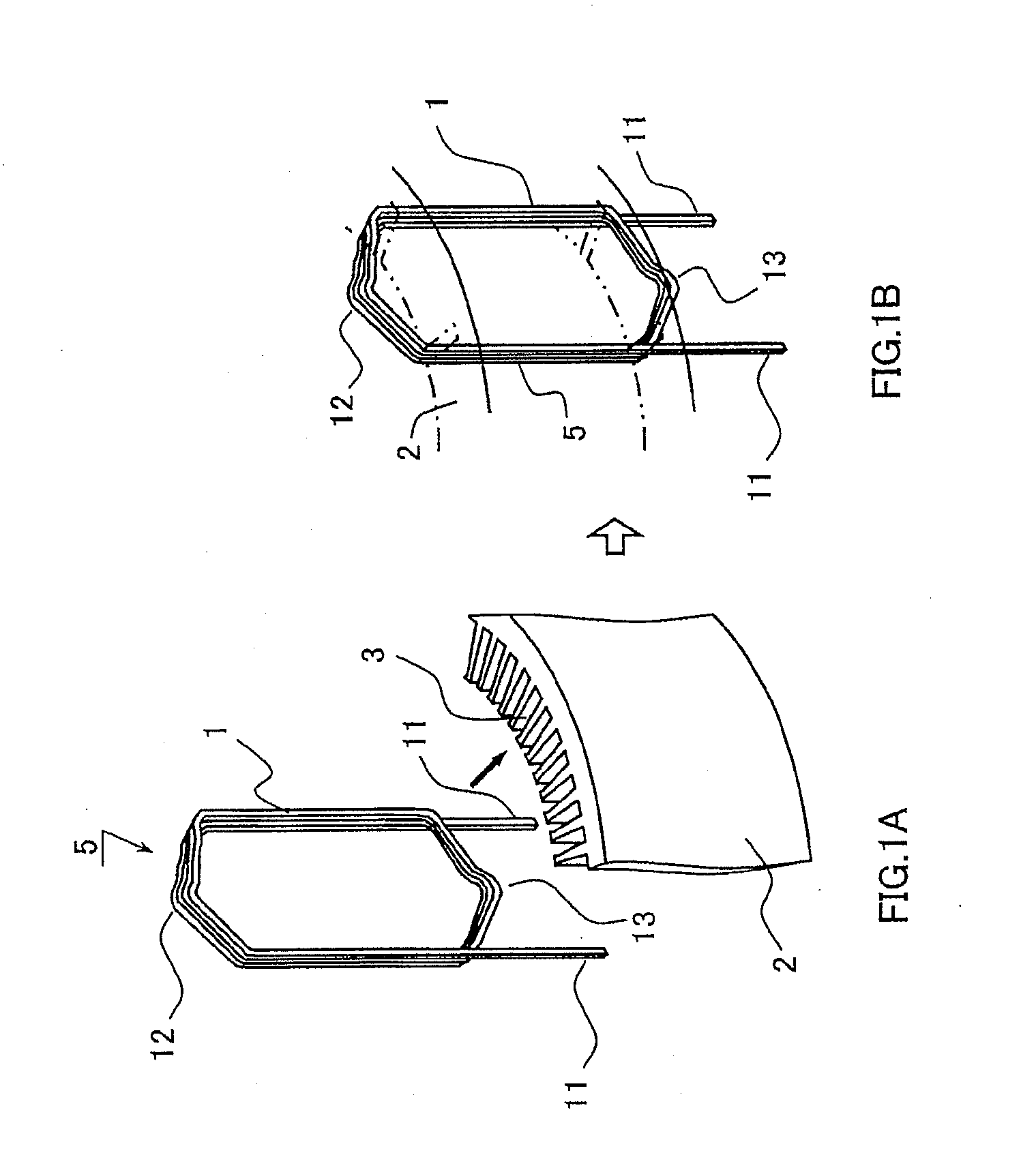
[0032]FIG. 1 shows a structure of a formed coil type of a first embodiment of the present invention. FIG. 1A is an oblique view prior to fitting of a formed coil 5 to a stator core 2, and the stator core 2 is shown notched. FIG. 1B is an oblique view showing a state in which the formed coil 5 is fitted to the stator core 2, and the outline of the stator core 2 is shown in a two-dot broken line. A coil wire 1 is a square wire made of copper and covered with a thin film of enamel resin. The stator core 2 is made of a rolled plate of approximately 1 mm in thickness which is punched out and laminated. The coil wire1 of the square wire of the same size or nearly the same size in length of two sides is continuously wound (three turns in FIG. 3), and a crown 12 which is an edgewise surface of the coil wire 1 double-wound and a coil terminal portion side crown 13 are bent and shaped in a crank shape so as to form a formed coil 5. The formed coil 5 is inserted into the stator slot 3 from the...

second embodiment

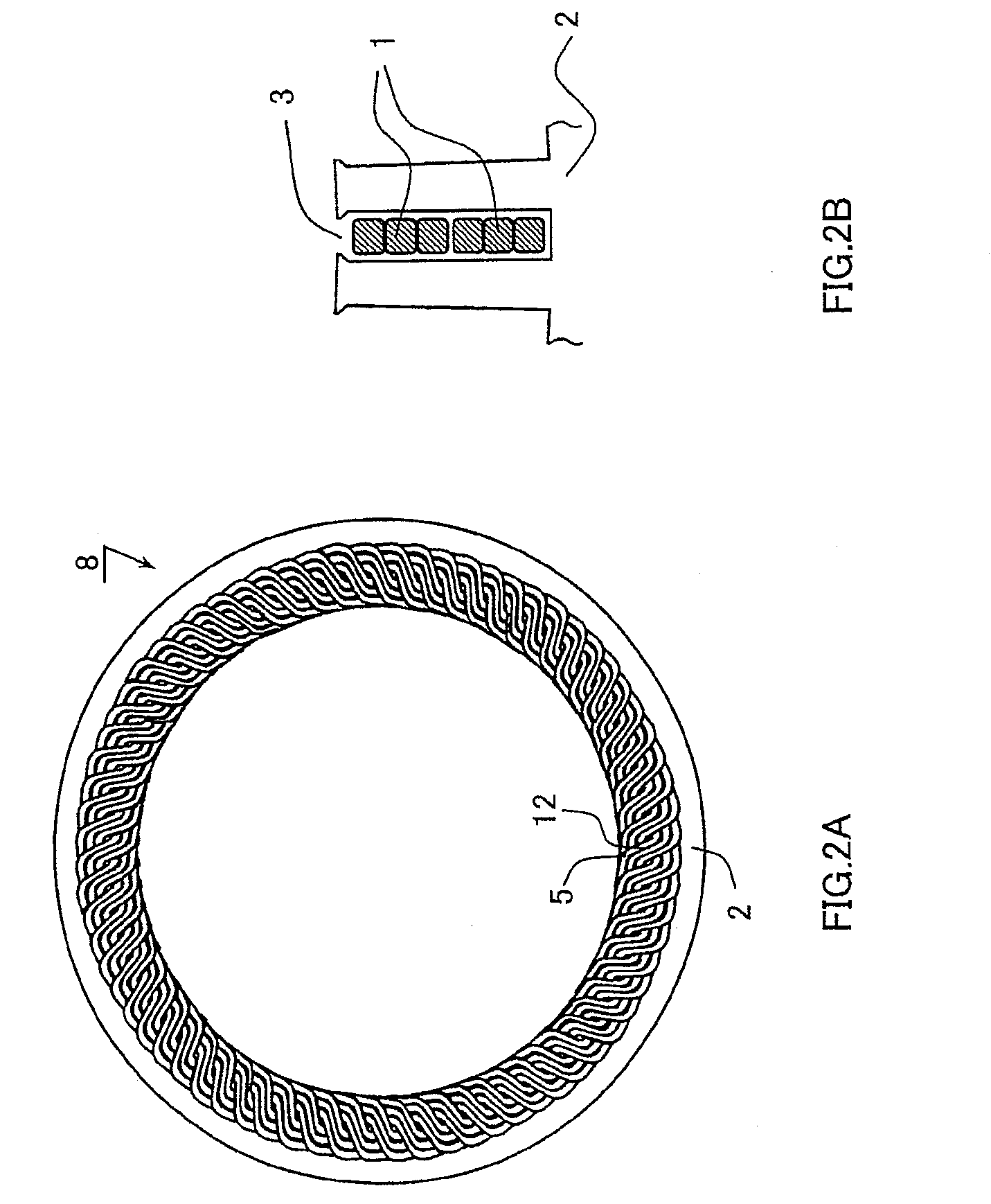
[0051]FIG. 12 shows a cross-sectional view of a portion of the stator slot 3 in a state in which a formed coil is formed by a square wire 1 coated with a fusion bond 14 of a second embodiment of the present invention and is fitted into a stator core 2. Two pieces of the square wire 1 are adhered to roughly make one piece of the square wire, thereby forming a formed coil. The fusion bond 14 is fused by heating at the predetermined temperature. Two pieces of the square wire 1 are overlapped and given heating and cooling, so that they can be adhered to each other. This achieves a structure in which 12 pieces of the square wire 1 are disposed within one slot. As a result, the flux density is further increased and the current density is reduced, thereby increasing efficiency as the rotary electric machine.


PUM

PropertyMeasurementUnit
Sizeaaaaaaaaaa
Electrical conductoraaaaaaaaaa
Widthaaaaaaaaaa

Abstract

In a distribution winding stator using a coil for a rectangular conductor, a coil end is made smaller than before, and the reduction in the current density is aimed, so that a rotary electric machine of a small size and a high power output is obtained. A conductive wire of a rectangular shape in cross section is double-wound, and is allowed to be shifted by the whole width of the wire having double-wound the crowns of both ends, and is formed to crank shape so as to become a length within the range of the intervals of the adjacent slots, so that the conductive wire is formed by being inserted into the slot of the stator.

Description

[0001]The present application is based on and claims priority of Japanese patent application No. 2006-284780 filed on Oct. 19, 2006, the entire contents of which are hereby incorporated by reference.BACKGROUND OF THE INVENTION[0002]1. Field of the Invention[0003]The present invention relates to a rotary electric machine such as a motor and an electric generator, a crank-shaped continuously winding coil, a distribution winding stator and the forming method thereof.[0004]2. Description of the Related Art[0005]A form of a coil winding of a stator includes a concentrated winding to concentratedly wind a coil on each pole cog and a distribution winding to wind a coil by striding across a plurality of slots with hetero-phase coils or in-phase coils mutually overlapped at a coil end. The stator of the concentrated winding can make the coil end small, and is effective for miniaturization and high efficiency of the rotary electric machine. On the other hand, the stator of the distribution wi...

Claims


Application Information

Patent Timeline
IPC IPC(8): H02K3/04H02K15/04H02K3/12
CPCH02K3/28Y10T29/49009H02K15/045H02K15/0414H02K15/063
Inventor NAGANAWA, TAKASHI
Owner HITACHI LTD
Why Eureka
Try Eureka