No Point of Contact Charging System

a charging system and point of contact technology, applied in the direction of inductance, disinfection, transportation and packaging, etc., can solve the problems of reducing efficiency, reducing the efficiency of the whole circuit, and limited monitoring and controlling of the charging state through detection. , to achieve the effect of effectively monitoring and controlling the charging state, preventing from being heated, and improving the efficiency of the entire circui

Active Publication Date: 2008-04-24
GE HYBRID TECH
View PDF3 Cites 65 Cited by
  • Summary
  • Abstract
  • Description
  • Claims
  • Application Information

AI Technical Summary

Benefits of technology

[0023]In accordance with the present invention, components for detecting a portable terminal, a battery pack or a foreign object that is placed on the pad of a non-contact charger, and effectively monitoring and controlling its charging state through the detection are added, so that the efficiency of the entire circuit is improved, and the foreign object can be prevented from being heated by induction heating.
[0024]Furthermore, a function of sterilizing a terminal is provided to a non-contact charging pad and also anions are generated therefrom, so that the terminal can be sanitarily used and nearby ambient air thereof can be kept fresh.
[0025]Furthermore, a primary core unit included in a non-contact charging pad is provided in a form such that the center portion thereof may be passed through, so that the structure thereof is simplified, charging is available at a defined location and, therefore, the usage efficiency thereof can be increased.

Problems solved by technology

However, when detecting the portable device or the battery pack placed on the non-contact charging pad, the conventional technology depends on a scheme for transmitting Radio Frequency (RF) carrier signals to the outside through a reader antenna, and then detecting whether return signals exist, so that it is problematic in that the detection of the battery pack and the monitoring and controlling of the charging state through the detection are limitedly performed.
Furthermore, in the case in which a coin, a metal pen, a pair of scissors or the like (hereinafter referred to as a foreign object), other than the battery pack or the portable device, are placed on the non-contact charging pad, power transmission is continuously performed, so that a problem occurs in that the foreign object placed on the non-contact charging pad is heated by induction heating.
Furthermore, the non-contact charging pad only has a function of charging terminals or battery packs, so that a problem occurs in that the efficiency thereof is lowered.

Method used


Image

  • No Point of Contact Charging System
  • No Point of Contact Charging System
  • No Point of Contact Charging System

Examples


Embodiment Construction

[0034]An embodiment of the present invention is described in detail with reference to the accompanying drawings below.

[0035]When it is determined that details of well-known functions or constructions related to descriptions of the present invention may unnecessarily make the gist of the present invention unclear, the details will be omitted.

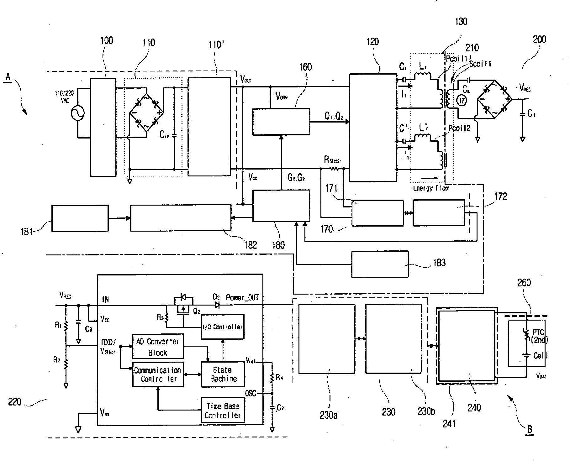
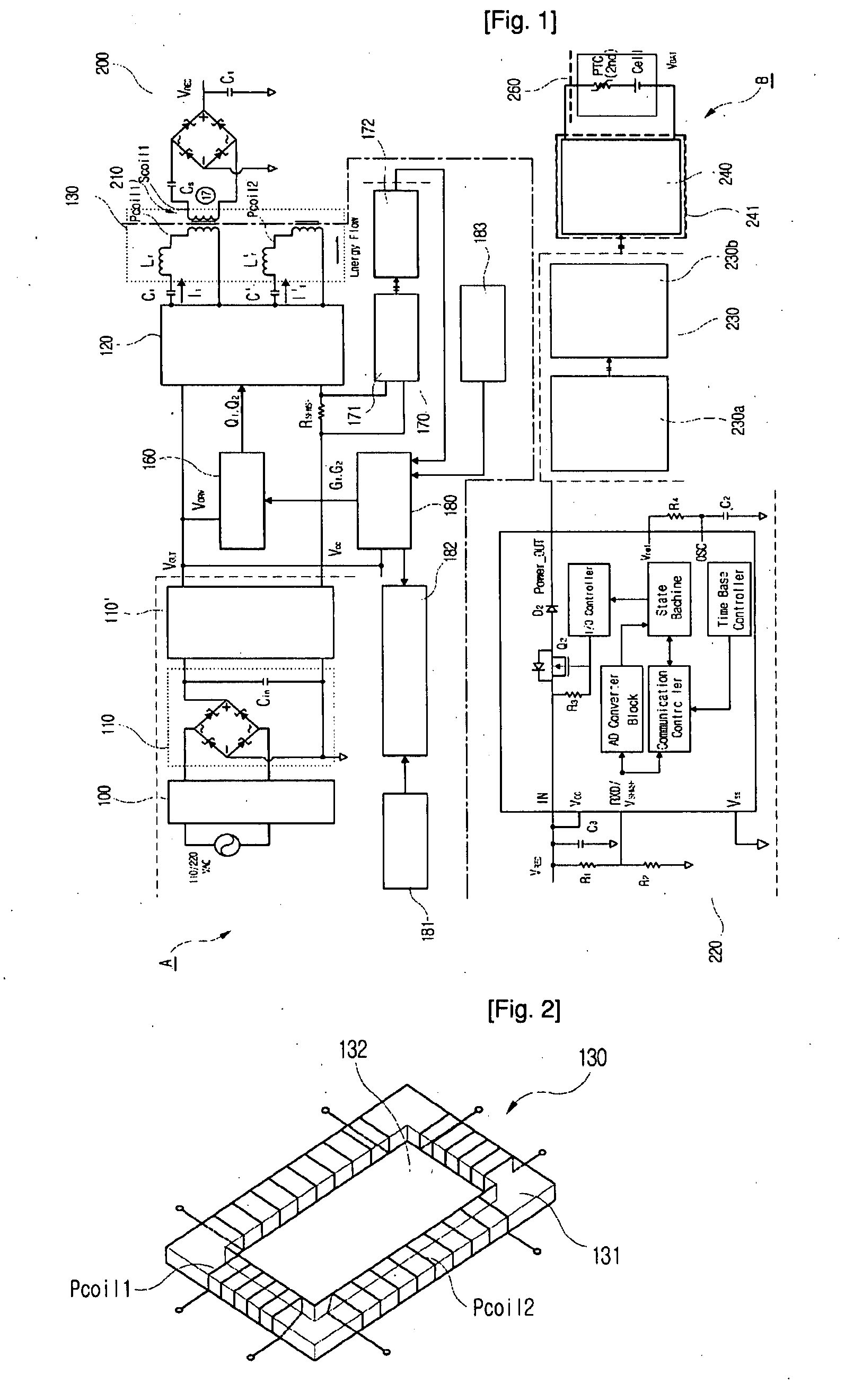
[0036]FIG. 1 is a block diagram showing the construction of a non-contact charging system according to the present invention.

[0037]The non-contact charging system according to the present invention includes a battery pack B charged by an induced electromotive force that is generated in a non-contact charger A supplied with power.

[0038]The non-contact charger A, as shown in FIG. 1, blocks electromagnetic waves caused by Alternating Current (AC) power (110 / 220 V) input using an electromagnetic wave filter 100 that is connected to the power input terminal of a wireless charging pad, and a primary rectification circuit 110 rectifies the AC power, the...


PUM


Abstract

Disclosed herein is a non-contact charging system. The non-contact charging system detects a portable terminal, a battery pack or a foreign object that is placed on the pad of a non-contact charger, and effectively monitors and controls its charging state through the detection, thus preventing such a foreign object placed on the pad from being heated by induction heating, and further causes anions to be generated during the charging of the portable terminal or the battery pack, thus sterilizing bacteria on a terminal and keeping ambient air thereof fresh.

Description

TECHNICAL FIELD[0001]The present invention relates, in general, to a no point of contact charging system and, more particularly, to a no point of contact charging system, which detects a portable terminal, a battery pack or a foreign object that is placed on the pad of a non-contact charger, and effectively monitors and controls its charging state through the detection, thus preventing such a foreign object placed on the pad, from being heated by induction heating, and which causes anions to be generated during the charging of the portable terminal or the battery pack, thus destroying bacteria on a terminal and keeping nearby ambient air fresh.BACKGROUND ART[0002]Generally, as communication and information processing technology are developed, the use of portable devices, such as mobile phones, that are convenient to carry is gradually increasing. With the development of technology, there is a trend in which new model terminals, the efficiency of which is improved, are being frequent...

Claims


Application Information

Patent Timeline
Patent Type & Authority Applications(United States)
IPC IPC(8): H02J7/00
CPCH02J7/00H02J7/025H01F38/14H02J50/12H02J50/60H02J50/80H02J7/00034Y02E60/10H04M1/17A61L2/02
Inventor CHO, KI-YOUNG
Owner GE HYBRID TECH
Why Eureka
Try Eureka