

Solid Electrolytic Capacitor
a capacitor and solid electrolytic technology, applied in capacitors, capacitor housing/encapsulation, electrical equipment, etc., can solve the problems of electromagnetic wave noise adversely affecting the electronic equipment, the noise generated by other electronic components than the cpu, and the increase of the high frequency component of the noise generated by such a device, so as to improve the high-frequency noise removal performance and prevent the leakage of electromagnetic waves
- Summary
- Abstract
- Description
- Claims
- Application Information
AI Technical Summary
Benefits of technology
Problems solved by technology
Method used
Image

Examples
first embodiment
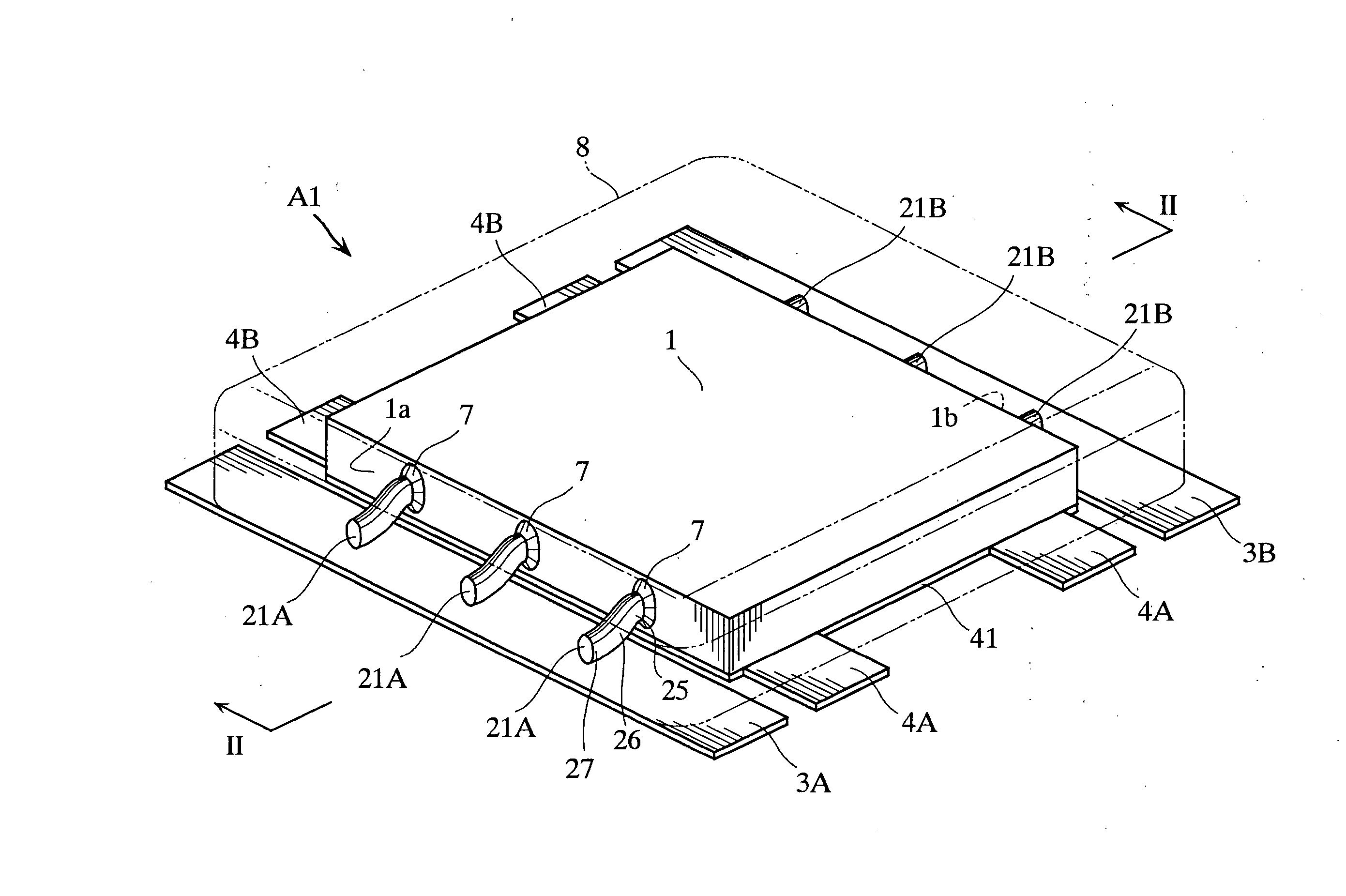
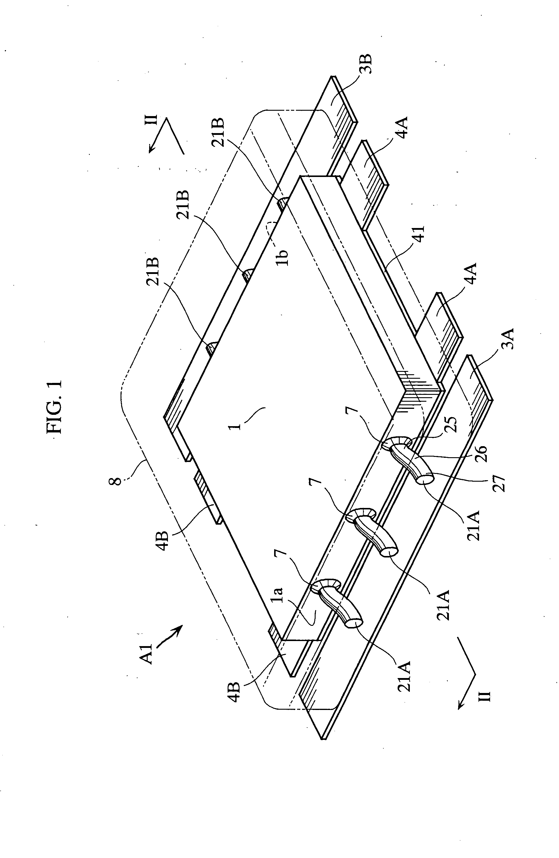
[0026]FIGS. 1 and 2 show a solid electrolytic capacitor according to the present invention. As shown in FIG. 1, the solid electrolytic capacitor A1 in this embodiment includes a porous sintered body 1, anode wires 21A and 21B, anode terminals 3A and 3B, cathode terminals 4A and 4B, and sealing resin 8.
[0027] The porous sintered body 1 is formed by compacting powder of niobium, which is a valve metal, into the form of a rectangular plate and then sintering the compacted body. On the porous sintered body 1, a dielectric layer (not shown) made of e.g. niobium pentoxide is formed. On the dielectric layer, a solid electrolytic layer (not shown) is formed. The solid electrolytic layer may be made of e.g. manganese dioxide or conductive polymer. As the material of the porous sintered body 1, any valve metal can be used, and tantalum may be used instead of niobium.
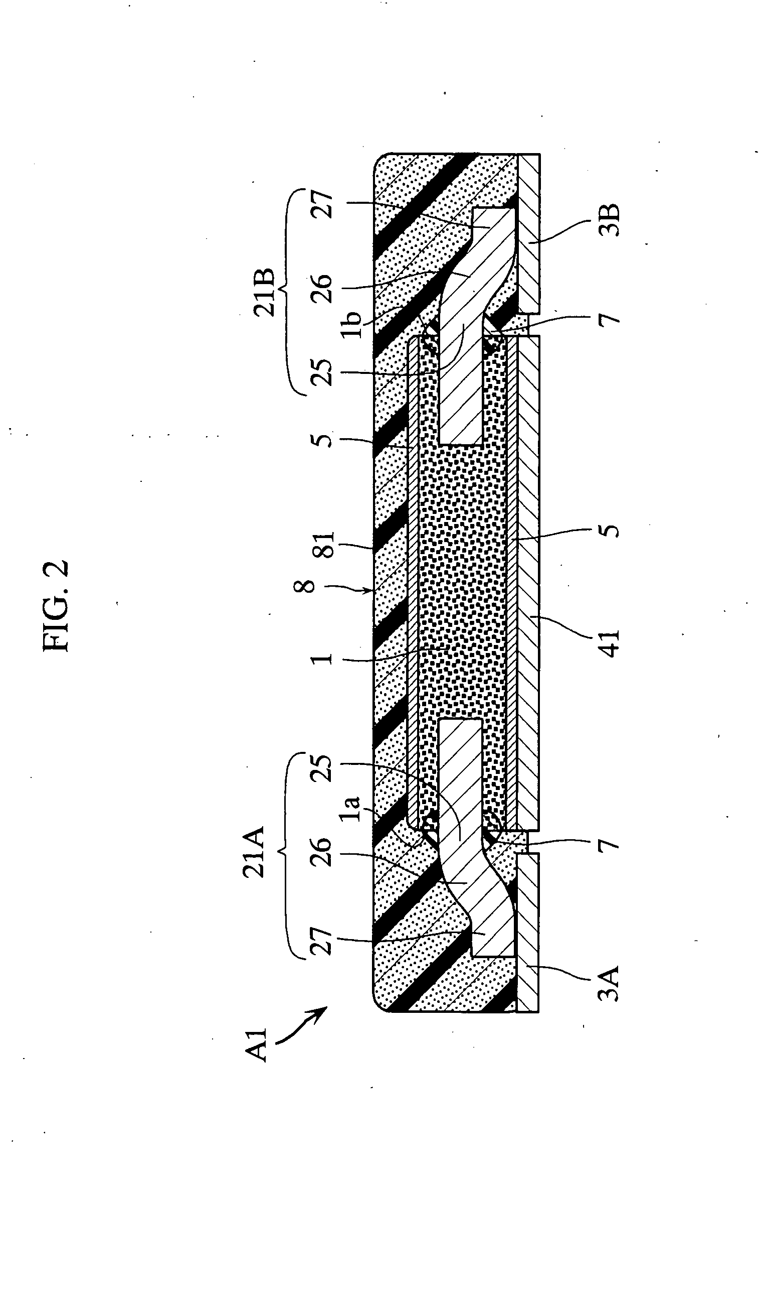
[0028] As shown in FIG. 2, a conductive layer 5 electrically connected to the solid electrolytic layer is formed on an outer su...
second embodiment
[0042]FIGS. 3-5 show a solid electrolytic capacitor according to the present invention. Unlike the solid electrolytic capacitor of the foregoing embodiment, the solid electrolytic capacitor A2 of this embodiment includes a metal cover 42 made of a ferromagnetic material.
[0043] As shown in FIG. 3, the metal cover 42 has a rectangular, entirely flat shape and is made of ferromagnetic metal. As the material of the metal cover 42, it is preferable to use a material which is ferromagnetic and has a relatively low electrical resistance, and Fe or 42 alloy (Fe-42% Ni) may be used. As shown in FIG. 4, the metal cover 42 covers the porous sintered body 1, the anode wires 21A, and 21B and so on. The metal cover 42 is bonded to the upper surface of the porous sintered body 1 via a conductive layer 5. With this structure, the metal cover 42 is electrically connected to the solid electrolytic layer (not shown) formed on the surface of the porous sintered body 1. Sealing resin 8 is loaded in a re...
third embodiment
[0048]FIGS. 6-8 show a solid electrolytic capacitor according to the present invention. Unlike the foregoing embodiments, the solid electrolytic capacitor A3 of this embodiment includes a ferromagnetic metal cover 6 which is not electrically connected to the anode terminals 3A, 3B and the cathode terminals 4A, 4B.
[0049] As shown in FIG. 6, the metal cover 6 has a rectangular, entirely flat shape and is made of a ferromagnetic material. As the ferromagnetic material, it is preferable to use a material which has a high relative magnetic permeability and a high electrical resistance, such as ferrite. As shown in FIG. 6, the metal cover 6 includes a top plate 6a, a bottom plate 6b, and side plates 6c and 6d. As shown in FIGS. 7 and 8, the porous sintered body 1 is sandwiched between the top plate 6a and the bottom plate 6b. An insulating resin film 71 is interposed between the top plate 6a and the porous sintered body 1. A resin film 71 is also interposed between the cathode metal plate...
PUM
 Abstract
Description
Claims
Application Information