IP multicast service system, switching device, and group selection transmission method used therefor

a multicast service system and switching device technology, applied in broadcast transmission systems, data switching networks, digital transmission, etc., can solve the problems of poor network efficiency, increased operation cost, and long switching tim

Inactive Publication Date: 2008-04-24
NEC CORP
View PDF12 Cites 8 Cited by
  • Summary
  • Abstract
  • Description
  • Claims
  • Application Information

AI Technical Summary

Problems solved by technology

In the L2 / L3 switch on the subscriber-side, the art described in the non-patent documents has problems, namely, (1) if a multicast group address of a provider is changed, an address to be received should be changed in units of IP-STBs, so that a procedure for changing setting for this is required and an operational cost is increased, and (2) there is no redundancy of a multicast route or a server and a service is not available in the case of a failure.
However, according to the above-described IP multicast control system, in the case of the art described in the above-described patent documents, a protocol sequence for multicast viewing upon switching due to a failure is running, so that this involves a problem such that it takes a long switching time.
In addition, since one side is always waiting as a spare system according to the IP multicast control system described in the non-patent documents, there is a problem such that an efficiency of using a server or a network is poor.
Further, the above-described patent documents and non-patent documents do not describe an art that can design an independent multicast group system in each network on the center side and the subscriber-side.

Method used


Image

  • IP multicast service system, switching device, and group selection transmission method used therefor
  • IP multicast service system, switching device, and group selection transmission method used therefor
  • IP multicast service system, switching device, and group selection transmission method used therefor

Examples


first exemplary embodiment

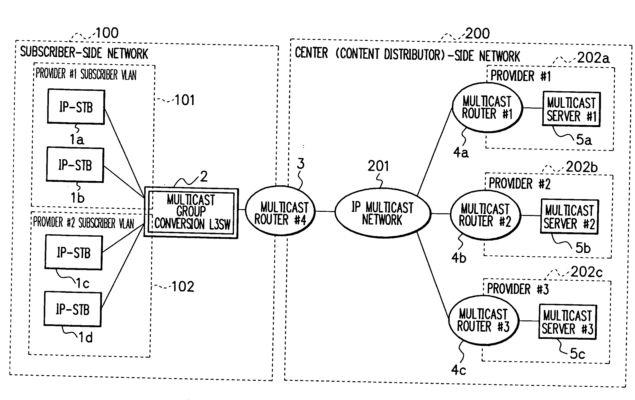
[0039]FIG. 3 is a block diagram showing a constitution of an IP multicast service system according to a first exemplary embodiment of the present invention. In FIG. 3, the IP multicast service system is configured by a center-side network 200 and a subscriber-side network 100.

[0040]The center-side network 200 is a network configuring a provider applying a service and is constructed by providers (#1 to #3) 202a to 202c for providing a multicast service, multicast servers (#1 to #3) 5a to 5c that accumulate a service such as an image in the providers (#1 to #3) 202a to 202c and can transmit it to the public, multicast routers (#1 to #3) 4a to 4c for routing an IP multicast packet, and the like. Each of the multicast routers (#1 to #3) 4a to 4c is connected to an IP multicast network 201.

[0041]The providers (#1 to #3) 202a to 202c are providers who intend to provide a service by means of multicast, wherein the multicast routers (#1 to #3) 4a to 4c and the multicast servers (#1 to #3) 5...

second exemplary embodiment

[0067]FIG. 10 is a block diagram showing a constitution of an IP multicast service system according to a second exemplary embodiment of the present invention. In FIG. 10, the basic structure of the IP multicast service system according to the second exemplary embodiment of the present invention is the same structure as that of the first exemplary embodiment according to the present invention shown in FIG. 3, however, the multicast group mapping table 6 is further devised.

[0068]In FIG. 10, there are two or more servers (the multicast servers (#1, #2) 5a, 5b) for transmitting a multicast packet in the provider (#1) 202a so as to realize redundancy. Therefore, according to the present embodiment, a multicast group mapping table 6a is configured by adding a redundancy item (setting of redundancy) to the multicast group mapping table 6 according to the first exemplary embodiment of the present invention.

[0069]Upon receipt of a viewing request from the IP-STB 1a, the multicast group conve...

third exemplary embodiment

[0077]FIG. 14 is a block diagram showing a constitution of an IP multicast service system according to a third exemplary embodiment of the present invention. In FIG. 14, the basic structure of the IP multicast service system according to the third exemplary embodiment of the present invention is the same as that of the second exemplary embodiment of the present invention shown in FIG. 10, however, the operation when the all servers [the multicast server (#1, #2) 5d, 5e] cannot provide a service is further devised.

[0078]According to the present embodiment, a multicast server 8 for emergency broadcast is connected to the multicast group conversion L3SW2. When the multicast group conversion L3SW2 detects unavailability of the service of the all servers, the multicast packet is transmitted from the multicast server 8 in place of the multicast packet to be essentially transmitted to the subscriber-side network 100.

[0079]In this way, according to the present embodiment, other than the adv...


PUM


Abstract

The object of the present invention is to provide an IP multicast service system which can design an independent multicast group system in each network on the center side and the subscriber-side. In an IP multicast service system according to the present invention including: a center-side network configured by a plurality of multicast servers; and a subscriber-side network configured by a plurality of IP-STBs (Internet Protocol-Set Top Boxes) for receiving a multicast packet transmitted from the multicast servers and reproducing the multicast packet as an image, a group design on the basis of an independent group address system on the center-side network and on the subscriber-side network can be made by converting a group address of the multicast packet transmitted and received between the center-side network and the subscriber-side network.

Description

[0001]This application is based upon and claims the benefit of priority from Japanese patent application No. 2006-283213 filed on Oct. 18, 2006, the disclosure of which is incorporated herein in its entirety by reference.BACKGROUND OF THE INVENTION[0002]1. Field of the Invention[0003]The present invention pertains to an IP multicast service system, a switching device, and a group selection transmission method used therefor, and particularly, the present invention pertains to a system for providing an IP (Internet Protocol) multicast service.[0004]2. Description of Related Art[0005]A typical network structure in an IP multicast service is shown in FIG. 1. A conventional network can be roughly divided into a center-side network 200 and a subscriber-side network 100.[0006]The center-side network 200 is constructed by providers 202a to 202c for providing a multicast service, multicast servers (#1 to #3) 5a to 5c that accumulate a service such as an image in the providers (#1 to #3) 202a...

Claims


Application Information

Patent Timeline
Patent Type & Authority Applications(United States)
IPC IPC(8): H04L12/56H04L47/2416
CPCH04L12/185H04L61/25H04L29/1233H04L12/4641H04L61/4552
Inventor OOGUSHI, SADAICHIROUSATOU, SOU
Owner NEC CORP
Why Eureka
Try Eureka