Adaptive controller for linearization of transmitter with impairments

a linearization controller and transmitter technology, applied in the field of transmitters, can solve the problems of reducing the accuracy of gain estimation, the complexity of solutions requiring powerful offline processing capabilities, and the variation of signal magnitude, so as to reduce the sensitivity to system impairments and the susceptibility of minimal system impairments

Inactive Publication Date: 2008-04-24
APPLE INC
View PDF27 Cites 28 Cited by
  • Summary
  • Abstract
  • Description
  • Claims
  • Application Information

AI Technical Summary

Benefits of technology

[0016] A controller for adaptive baseband linearization of radio transmitters has reduced sensitivity to system impairments in the transmitter chain such as gain variation, phase noise or modulation / demodulation frequency instability. The controller provides separate estimation and cancellation of linear gain variations in order to achieve minimal susceptibility to these system impairments. Values of a linear and a nonlinear digital complex gain blocks, called respectively a gain regulation block and a predistortion block, are independently adjusted. The gain blocks are cascaded with the linearized transmitter and are managed by two different adaptive controllers. The gain regulation block approximates the linear gain of the closed-loop adaptive linearization system or its inverse, while the predistortion block approximates the inverse of the normalized nonlinear transmitter gain (of unity average magnitude and zero average phase).
[0018] Cancellation of lower-frequency system impairments affecting the magnitude and phase stability of the adaptive feedback signals is achieved using faster estimation of the average closed-loop system gain to provide gain- and phase-normalized feedback signals for estimation of the transmitter nonlinearity. Normalization of the adaptive feedback signals is achieved for the average signal values while the instantaneous ones can be subjected to random linear magnitude and phase variations. The lowest frequency of the variations is equal to the frequency of closed-loop gain estimation performed by the gain regulation controller, termed here ‘chopping frequency’, which is normally set to be more than 2 decades larger than the cut-off frequency of the predistortion controller. Reduction of the complexity of the predistortion controller is achieved by using phase normalized feedback signals to help minimize the overall increase of system complexity due to the gain regulation controller.

Problems solved by technology

Change of the average transmitter gain over time, which can be caused by different ambient factors, may significantly reduce the accuracy of gain estimation especially in cases when the predistortion process has different settling time constants over dynamic range.
A problem arises when in addition to the systematic gain changes there are system impairments in the same bandwidth causing random variations of the signal magnitude or phase, where the latter could be the result of phase noise or modulation / demodulation frequency instability.
Some of the major disadvantages of current systems are dependency on test signals or specific signaling formats for identification of such system impairments, as well as the complexity of the solutions requiring powerful offline processing capabilities.
Although exploiting the idea of two separate predistortion blocks—one for compensation of transmitter nonlinearity and another for the rest of the system impairments (most of which are of linear nature), the solution lacks generality due to the use of designated test sequences for nonlinearity estimation and constellation models for impairment identification.
Moreover, the level of complexity of the suggested identification and compensation procedures poses serious questions about the efficiency of its implementation.
A major drawback of the proposed system is that the measurements are conducted by stimulating the amplifier with designated reference bi-tone signals.
In addition, there is a fair amount of computational complexity involved in the approximation process.
Second, the forward model is used to generate noiseless signals applied as reference inputs to an inverse polynomial model of the amplifier.
Implementation of polynomial nonlinearity estimation involves computationally expensive operations like raising signal samples to a power larger than 2 as well as a multi-step derivation of the corresponding inverse polynomials performing the predistortion.
Notwithstanding their complexity, performance or efficiency, the existing solutions demonstrate the common disadvantage of being restricted to particular devices in the transmitter chain, such as quadrature modulator sections, that cause a particular type of gain imbalance, crosstalk or DC level bias.
A common disadvantage of the above-cited solutions is the lack of generality in the treatment of transmit channel impairments, which are often limited to a single functional block of the transmitter chain and assumed to be linear in nature.
The suggested calibration or adaptive procedures are explicitly designed to improve the performance of two-channel transmitters and, thus, their upgrade for multi-channel transmitters is not straightforward.
Moreover, application of these techniques in a system for transmitter linearization would require a significant amount of extra computational or hardware resources to be dedicated for channel imbalance compensation because of the high degree of incompatibility between the existing hardware-efficient linearization algorithms and the quadrature modulator algorithms.

Method used


Image

  • Adaptive controller for linearization of transmitter with impairments
  • Adaptive controller for linearization of transmitter with impairments
  • Adaptive controller for linearization of transmitter with impairments

Examples


Embodiment Construction

[0031] In the following description, reference is made to the accompanying drawings that form a part hereof, and in which is shown by way of illustration specific embodiments in which the invention may be practiced. These embodiments are described in sufficient detail to enable those skilled in the art to practice the invention, and it is to be understood that other embodiments may be utilized and that structural, logical and electrical changes may be made without departing from the scope of the present invention. The following description is, therefore, not to be taken in a limited sense, and the scope of the present invention is defined by the appended claims.

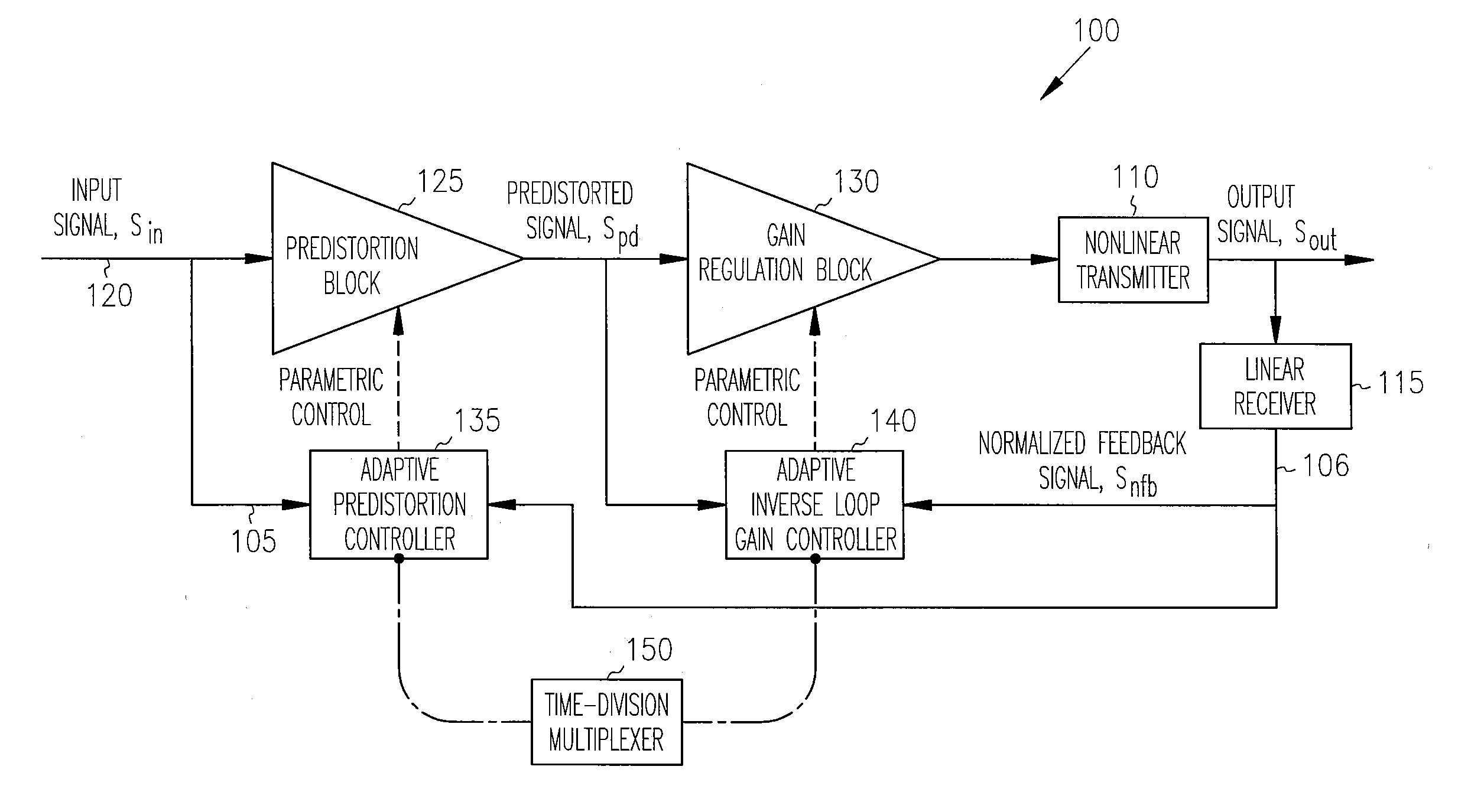
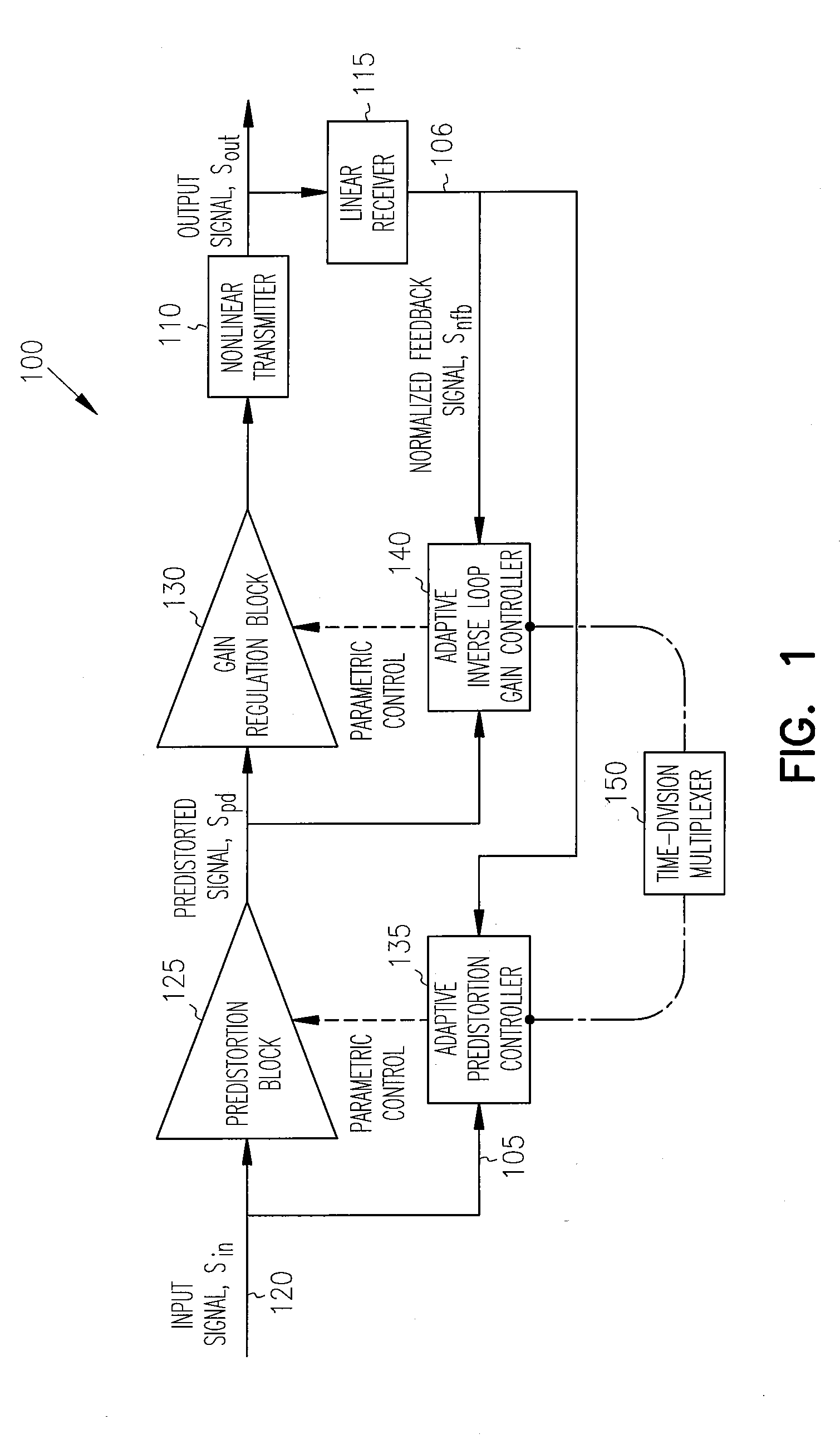
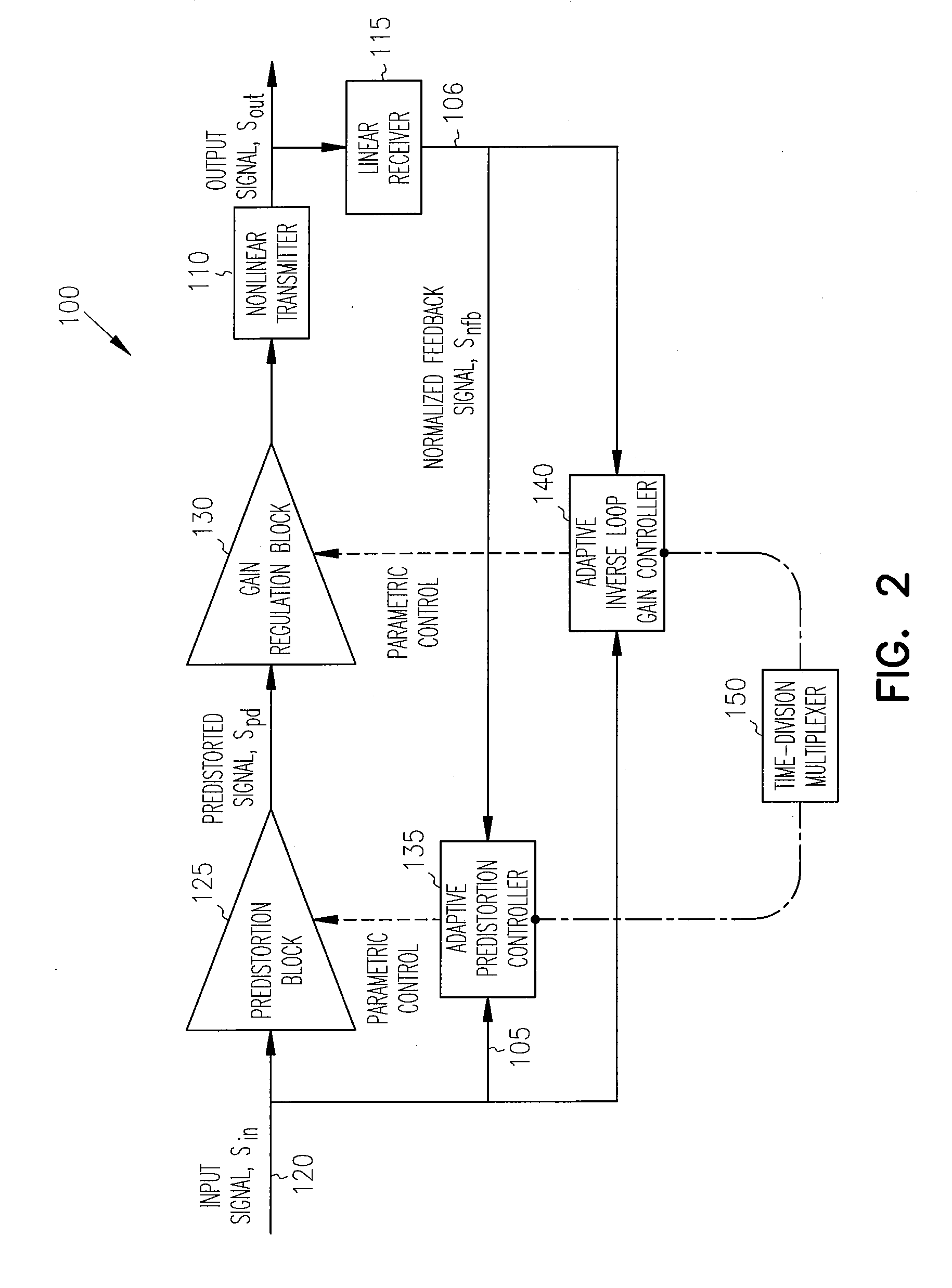
Adaptive Linearization Controller with Reduced Sensitivity to System Impairments: Gain, Phase or Frequency Variation

[0032] An adaptive transmitter linearization loop 100 in FIG. 1 provides effective cancellation of gain, phase or frequency variations in adaptive loops for transmitter linearization, which are composed of two...


PUM


Abstract

An adaptive controller for linearization of transmitters using predistortion of the input signal has reduced sensitivity to impairments such as gain variation, phase noise or modulation / demodulation frequency instability by linearizing an adaptively normalized gain provided through a separate estimation and cancellation of linear gain variations. Values of a nonlinear and a linear gain blocks, cascaded with the linearized transmitter and called respectively a predistortion block and a gain regulation block, are independently adjusted by two different adaptive controllers. In one embodiment, four banks of real gain elements compose the predistortion block and realize an arbitrary step-wise approximation of a generalized 2×2 transmit gain matrix of nonlinear functions. In a further embodiment cancellation of a DC level bias multi-channel impairment is provided by an adaptively adjusted signal adder inserted in the transmit chain between the predistortion block and the linearized transmitter.

Description

INCORPORATION BY REFERENCE [0001] This application is a divisional of U.S. patent application Ser. No. 10 / 321,045 filed Dec. 16, 2002, which is hereby incorporated by reference and made a part hereof. [0002] This application is also related to U.S. patent application Ser. No. 10 / 321,011 filed Dec. 16, 2002 (now U.S. Pat. No. 7,251,290), which is hereby incorporated by reference.FIELD OF THE INVENTION [0003] The present invention relates to transmitters, and in particular to an adaptive linearization controller for a transmitter. BACKGROUND OF THE INVENTION [0004] Some signal transmitters for cellular communications utilize QAM (quadrature amplitude modulation) to increase the number of signals that can be transmitted on a given channel. QAM is a method of combining two amplitude-modulated (AM) signals into a single channel to effectively double the effective bandwidth. QAM is used with pulse amplitude modulation (PAM) in digital systems, especially in wireless applications. [0005] I...

Claims


Application Information

Patent Timeline
Patent Type & Authority Applications(United States)
IPC IPC(8): H04L27/36H03F1/32H03F3/45
CPCH03F1/3211H04L27/368H03F3/45968H03F1/3247
Inventor RASHEV, PETER ZAHARIEVTHOLL, DAVID M.
Owner APPLE INC
Why Eureka
Try Eureka