[0008]It is an object of the present invention to provide a valve control device or / and a valve control method for an internal
combustion engine, which can promote homogenization of an air-fuel mixture in all operation areas, and also can simplify the control and structure thereof.
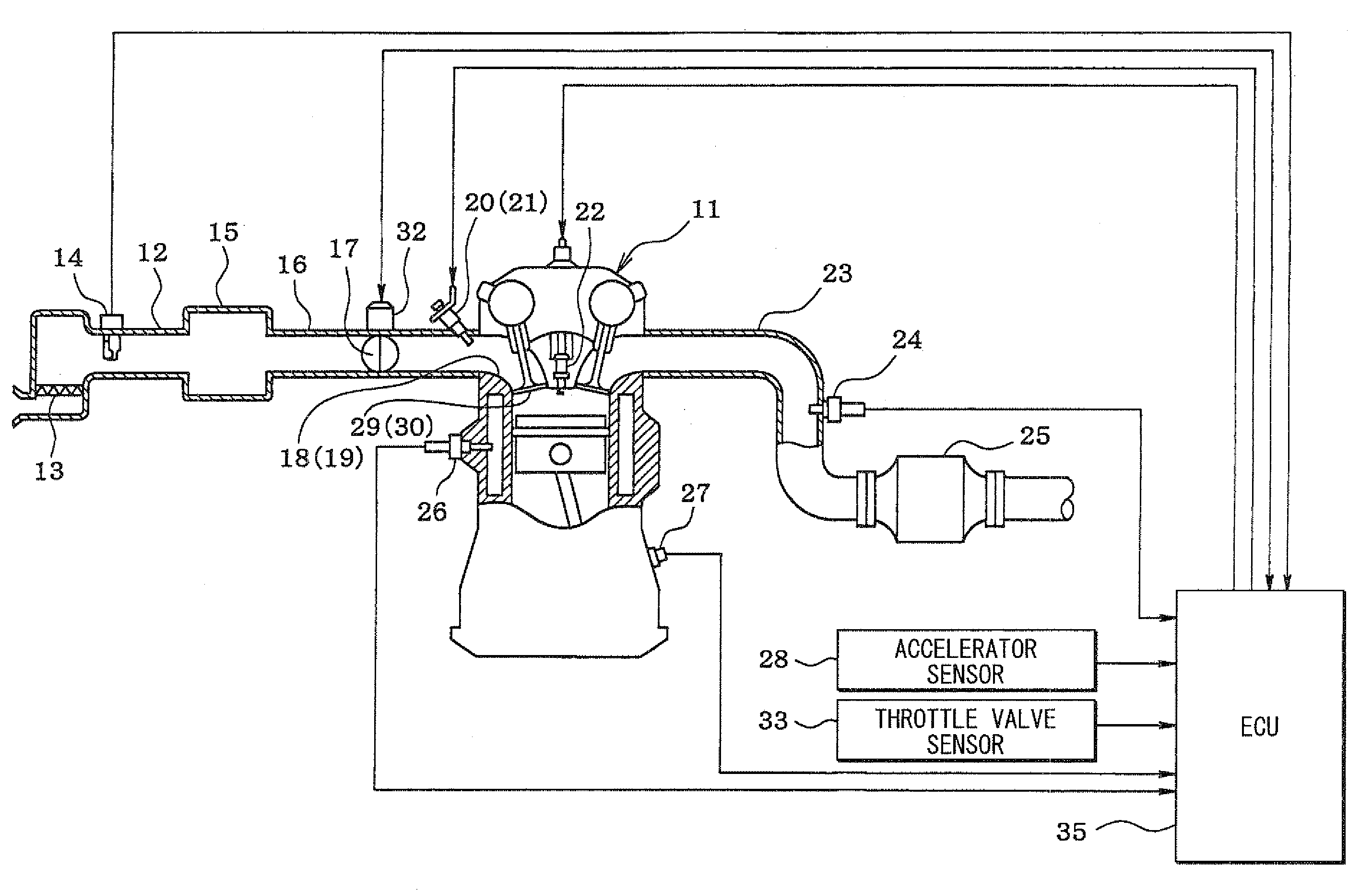
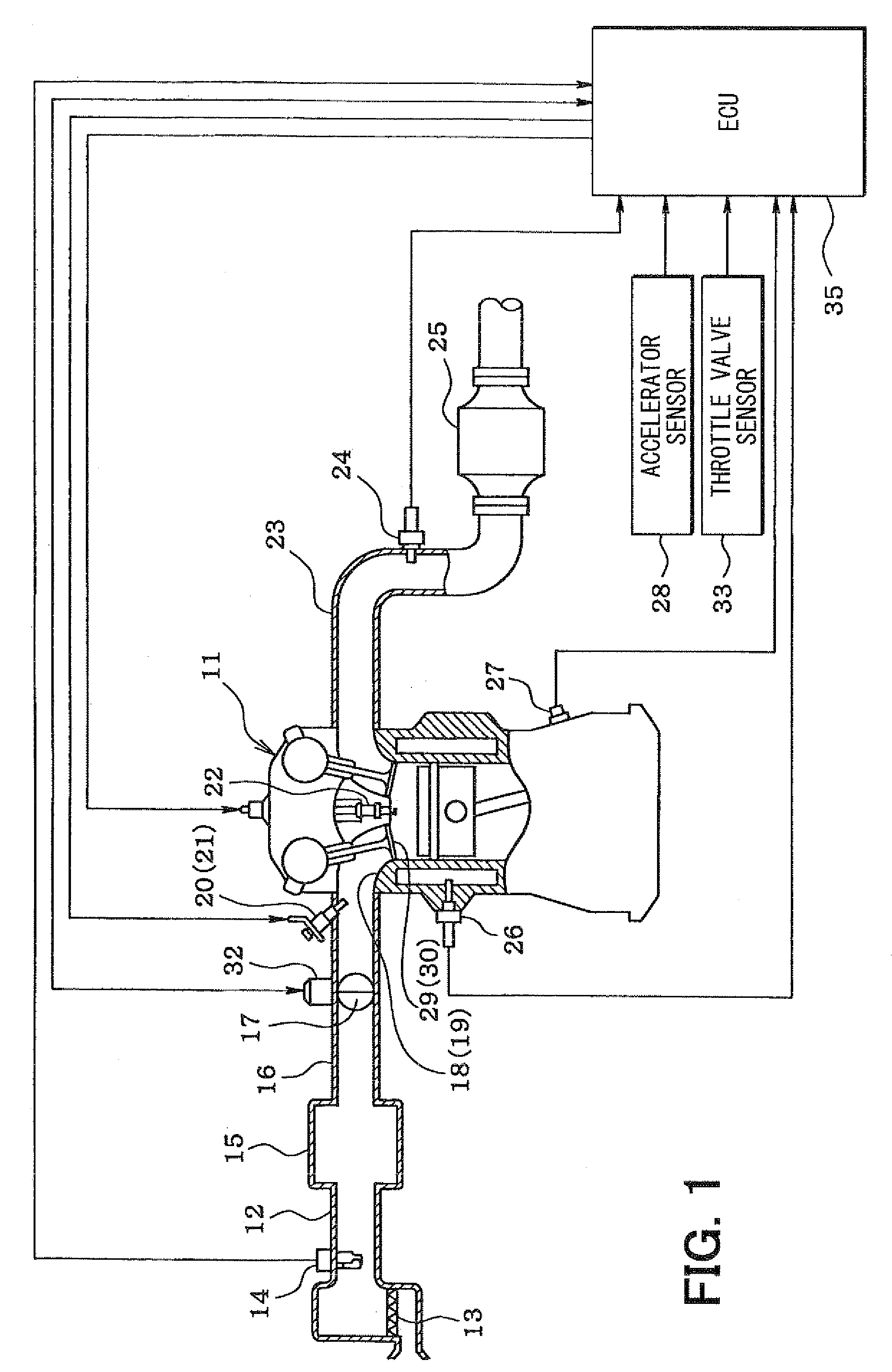
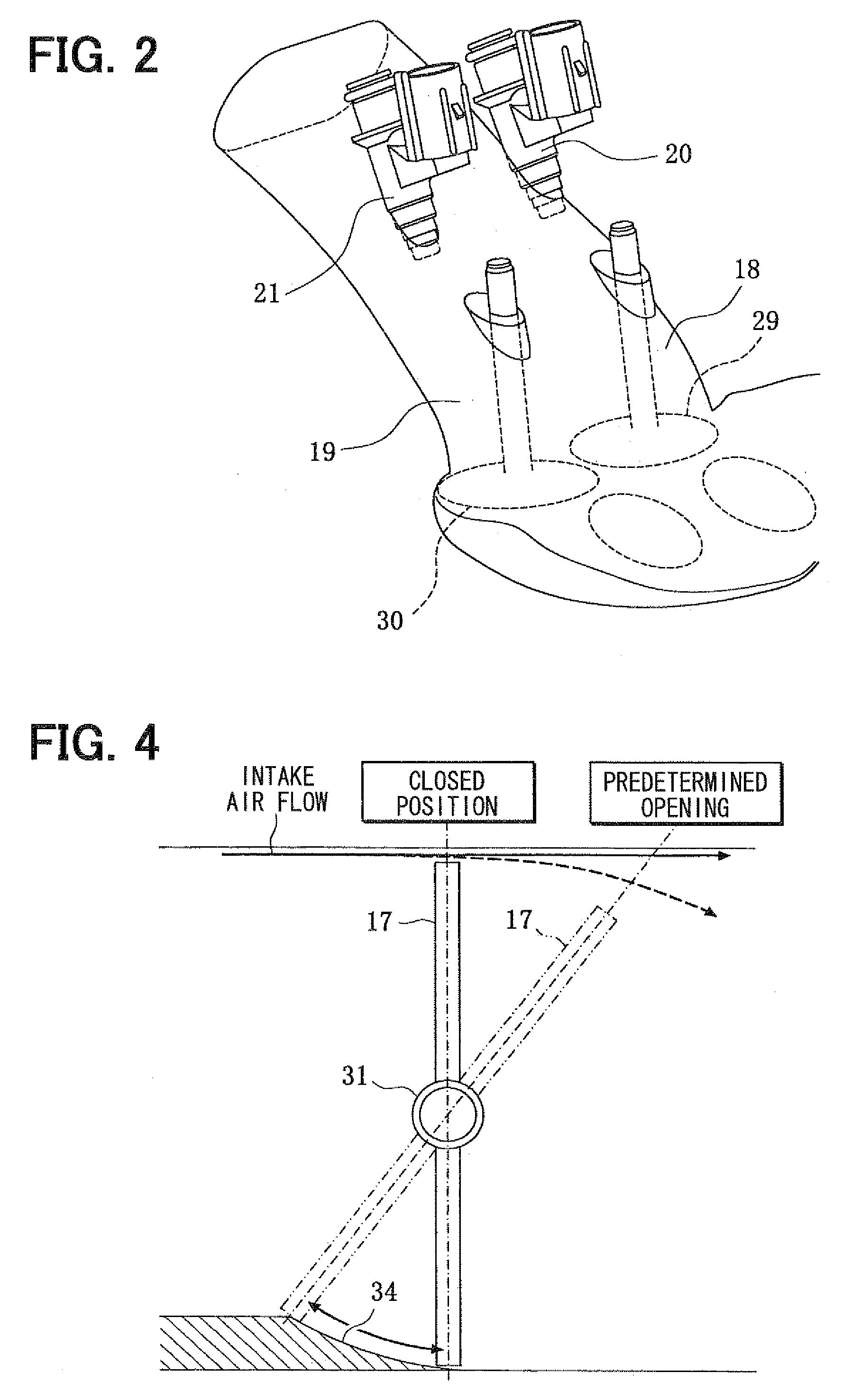
[0010]With this arrangement, when the opening degree of the intake throttle valve is substantially equal to or less than the predetermined value, the intake air mainly flows through the first intake port to generate a swirl flow in the cylinder, while the fuel is injected from the first fuel injection valve to the first intake port Thus, it can promote the homogenization of an air-fuel mixture. In contrast, when the opening degree of the intake throttle valve is substantially larger than the predetermined value, the intake air flows through both of the first and second intake ports, while the fuel is injected from both the first and second fuel injection valves to the respective first and second intake ports. Thus, it can also promote the homogenization of an air-fuel mixture. As a result, the homogenization of the air-fuel mixture can be promoted in all operation areas from a
low load operation area where an opening degree of the intake throttle valve is small to a
high load operation area where an opening degree of the intake throttle valve is large.
[0011]Since the intake air amount can be adjusted according to the opening degree of the intake throttle valve to control the occurrence of the swirl flow, the drastic change (torque shock) of the intake air amount hardly occurs due to the opening and closing of the intake throttle valve. In order to prevent the drastic change of the intake air amount, a complicated control is also not required, thereby simplifying the control of the intake throttle valve.
[0012]Since the intake throttle valve can have a function of adjusting the amount of intake air, and also a function of generating a swirl flow, a valve for adjusting the intake air amount and a valve for generating the swirl flow do not need to be provided independently, thereby simplifying the structure and satisfying the demand for cost reduction.
[0013]According to another aspect of the present invention, a valve control device for an internal
combustion engine includes an intake manifold for defining an intake air passage having first and second intake ports which are located at a downstream side of the intake air passage for each cylinder of the engine, an intake throttle valve located in the intake air passage at an upstream side of the first and second intake ports, a first fuel injection valve located to inject fuel to the first intake port, and a second fuel injection valve located to inject the fuel to the second intake port. The intake throttle valve is located such that intake air flows into mainly the first intake port to generate a swirl flow when an opening degree of the intake throttle valve is not larger than a predetermined value, and flows into both the first and second intake ports when the opening degree of the intake throttle valve is larger than the predetermined value, and a
control unit controls the first fuel injection valve and the second fuel injection valve in accordance with the opening degree of the intake throttle valve. Furthermore, a bore member is located in the intake air passage at a position adjacent to the intake throttle valve to prohibit a flow of the intake air to the second intake port when the opening degree of the intake throttle valve is not larger than the predetermined value. Accordingly, it is possible to control the swirl flow from the first intake port while keeping a substantially closing state of the second intake port when the opening degree of the intake throttle valve is not larger than the predetermined value. As a result, it can promote homogenization of the air-fuel mixture in all operation areas, and also can simplify the structure in the intake manifold.
[0015]According to another aspect of the present invention, a valve control method for an internal
combustion engine includes a step of detecting an opening degree of an intake throttle valve that located in the intake air passage at an upstream side of the first and second intake ports, a step of determining whether the opening degree of the intake throttle valve is larger than a predetermined value, a step of controlling the intake throttle valve such that intake air flows into mainly the first intake port to generate a swirl flow when the opening degree of the intake throttle valve is not larger than a predetermined value, and flows into both the first and second intake ports when the opening degree of the intake throttle valve is larger than the predetermined value, and a step of controlling a first fuel injection valve and a second fuel injection valve to allow an injection of the fuel from the first fuel injection valve into the first intake port when the opening degree of the intake throttle valve is not larger than about the predetermined value, and a step of controlling the first fuel injection valve and the second fuel injection valve to allow injections of the fuel from both the first fuel injection valve and the second fuel injection valve when the opening degree of the intake throttle valve is larger than about the predetermined value. Accordingly, the homogenization of the air-fuel mixture can be promoted in all operation areas from a
low load operation area where an opening degree of the intake throttle valve is small to a
high load operation area where an opening degree of the intake throttle valve is large.


