
Composition for preparing emitter, method of preparing the emitter using the composition, emitter prepared using the method and electron emission device including the emitter

a technology of carbon nanotubes and compositions, applied in the direction of electrode systems, electric discharge tubes/lamps, discharge tubes luminescnet screens, etc., can solve the problems of fiber type carbon nanotubes formed of particle type materials, and poor uniformity, so as to achieve easy regulation and less expensive

Inactive Publication Date: 2008-05-01
SAMSUNG SDI CO LTD
View PDF4 Cites 13 Cited by
  • Summary
  • Abstract
  • Description
  • Claims
  • Application Information

AI Technical Summary

Benefits of technology

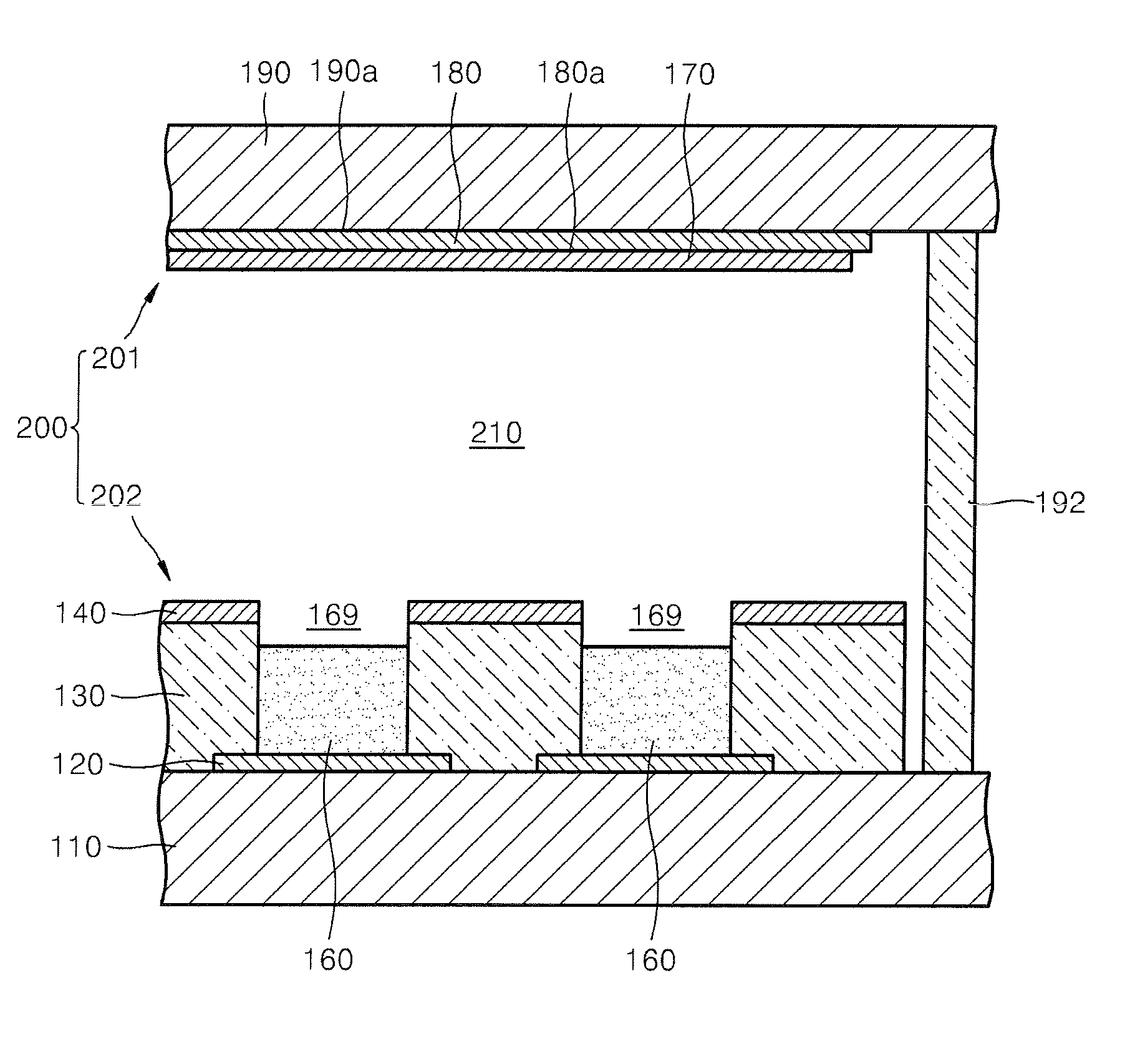
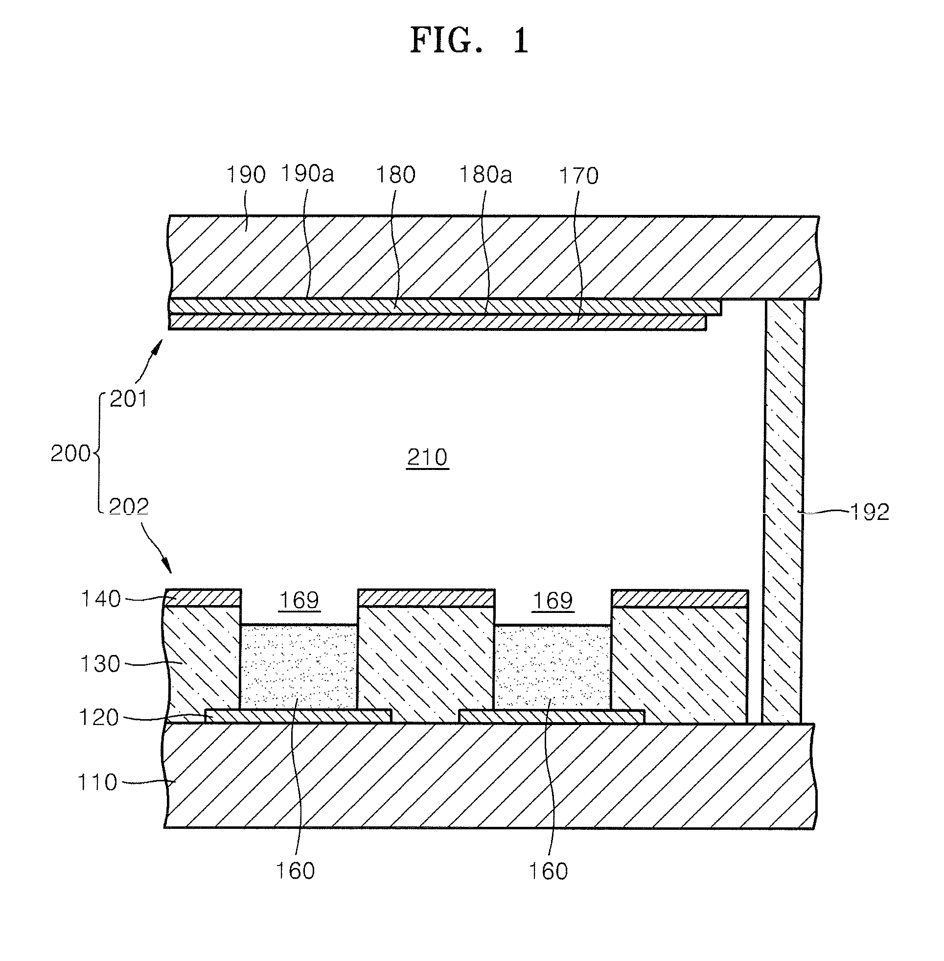
[0012]Aspects of the present invention provide a composition for an emitter by which the emitter can be prepared using a less expensive method than that using conventional carbon nanotubes in which a pattern can be formed by easily regulating the size of the manufactured emitter, using an ink jet method, without using an additional patterning method. Additional aspects of the present invention include a method of preparing the emitter using the composition for forming the emitter, an emitter prepared using the method and an electron emission device including the emitter.

Problems solved by technology

However, commonly used fiber type carbon nanotubes have a high field enhancement factor, β. Materials of fiber type carbon nanotubes have many problems such as bad uniformity, a short lifetime, and the like.
Fiber type carbon nanotubes manufactured using paste, ink, slurry, or the like, have manufacturing problems compared with carbon nanotubes formed of particle type materials.
In addition, fiber type materials are very expensive.
However, since carbon nanotubes, graphite fibers, or the like, which are used in conventional ink compositions for forming emitters, have a high aspect ratio and high field enhancement factor, β, these forms are not suitable for preparing an emitter by the ink jet method.

Method used


Image

  • Composition for preparing emitter, method of preparing the emitter using the composition, emitter prepared using the method and electron emission device including the emitter
  • Composition for preparing emitter, method of preparing the emitter using the composition, emitter prepared using the method and electron emission device including the emitter
  • Composition for preparing emitter, method of preparing the emitter using the composition, emitter prepared using the method and electron emission device including the emitter

Examples


Embodiment Construction

[0021]Reference will now be made in detail to the present embodiments of the present invention, examples of which are illustrated in the accompanying drawings, wherein like reference numerals refer to the like elements throughout. The embodiments are described below in order to explain the present invention by referring to the figures.

[0022]Aspects of the present invention provide an emitter in which manufacturing costs can be remarkably decreased, using an ink jet method, as well as a composition for the emitter which is more suitable than carbon nanotubes.

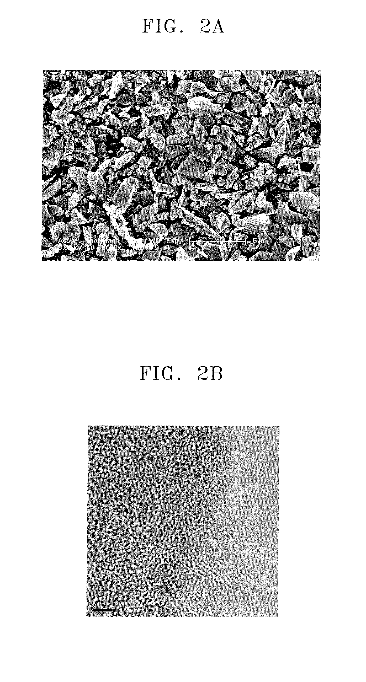
[0023]Aspects of the present invention also provide that the composition for the emitter includes carbide-derived carbon prepared using a method in which carbide compounds are thermochemically reacted with halogen-containing gases to remove all elements of the carbide compounds except carbon, as well as an organic solvent and a dispersant.

[0024]The carbide-derived carbon may be prepared using a method in which carbide compounds a...


PUM

PropertyMeasurementUnit
temperatureaaaaaaaaaa
aspect ratioaaaaaaaaaa
mole ratioaaaaaaaaaa

Abstract

A composition for preparing an emitter including: flake type carbide-derived carbon which is prepared by thermochemically reacting carbide compounds with halogen-containing gases to extract all elements of the carbide compounds except carbon, an organic solvent and a dispersant. A method of preparing the emitter using the composition for forming the emitter, an emitter prepared using the method and an electron emission device. The emitter has good uniformity and a long lifetime. It can be prepared using a more inexpensive method than using conventional carbon nanotubes. A pattern can be formed by easily regulating the size of the manufactured emitter using an ink jet printer. Non-uniform emission generated by residue when using a conventional printing method can be avoided. Thus, a micro electrode, in which an arc discharge does not occur even in the presence of a strong electric field, can be conveniently manufactured.

Description

CROSS-REFERENCE TO RELATED APPLICATIONS[0001]This application claims the benefit of Korean Application No. 2006-107459, filed on Nov. 1, 2007, in the Korean Intellectual Property Office, the disclosure of which is incorporated herein by reference.BACKGROUND OF THE INVENTION[0002]1. Field of the Invention[0003]Aspects of the present invention relate to a composition for an emitter where the composition includes carbide-derived carbon, a method of preparing the emitter using the composition, an emitter prepared using the method and an electron emission device. More particularly, aspects of the present invention relate to a composition for an emitter in which the emitter can be prepared to have good uniformity and a long lifetime using a less expensive method than that using conventional carbon nanotubes and in which a pattern can be formed by easily regulating the size of the manufactured emitter, using an ink jet method, without using an additional patterning method; as well as the m...

Claims


Application Information

Patent Timeline
Patent Type & Authority Applications(United States)
IPC IPC(8): H01J1/62B05D5/12H01B1/04
CPCH01J1/304H01J2201/30446H01J9/025B82Y40/00
Inventor KIM, YOON-JINKIM, JAE-MYUNGMOON, HEE-SUNG
Owner SAMSUNG SDI CO LTD
Learn More