Transmission scheme dependent control of a frame buffer

a frame buffer and transmission scheme technology, applied in the field of transmission scheme dependent control of a frame buffer, can solve the problems of error concealment algorithm not being able to utilize partially correct frames, application layer face frame loss, and buffer occupancy, so as to increase the length of the frame buffer and reduce data

Inactive Publication Date: 2008-05-01
NOKIA CORP
View PDF2 Cites 39 Cited by
  • Summary
  • Abstract
  • Description
  • Claims
  • Application Information

AI Technical Summary

Benefits of technology

[0028]According to the present invention, a frame buffer is comprised in a receiver and buffers frames that are received from a transmitter, which transmits said frames according to said frame transmission scheme. A change in said frame transmission scheme may affect a required length of said frame buffer. To keep the length of the frame buffer at a minimum, and thus to reduce the delay encountered when extracting the frames from the frame buffer for further processing (e.g. decoding or rendering of the frames at a constant frame rate), it is advantageous that the length of the frame buffer is controlled under consideration of said change in said frame transmission scheme. Therein, the control of the length of said frame buffer does not only have to be based on said change of said transmission scheme. Said control may be based on additional parameters, such as for instance characteristics of a transmission network or link over which said frames are transmitted, as for instance the average or maximum transmission delay. Said control of said length of said frame buffer (corresponding to the buffering time) may for instance be handled by a buffer control unit by performing a frame insertion using error concealment or by causing a decoder that decodes said frames to perform time scaling to slow down the decoding and playback of the sequence of frames extracted from the frame buffer, and hence, increase the buffering time.
[0029]According to an exemplary embodiment of the present invention, said change in said frame transmission scheme is a future change. A length of said frame buffer is thus controlled under consideration of a future change in said frame transmission scheme, i.e. a change in said frame transmission scheme is anticipated at the receiver proactively. Being able to control the length of said frame buffer in advance, i.e. before an actual change in said transmission scheme occurs, has the advantage that the receiver may prepare for the consequences of said change in said transmission scheme and may compensate said consequences in due time. Furthermore, the receiver may have more degrees of freedom left in deciding when to compensate said consequences. For instance, if said change in said frame transmission scheme causes a temporal gap in the sequence of frames extracted from the frame buffer for decoding and / or playback, a buffer control algorithm at the receiver may be able to perform frame insertion or to cause a decoder to perform time scaling in a controlled manner during a specific period selected to minimize the subjective quality distortion, for instance a period of low signal or high noise.
[0032]According to an exemplary embodiment of the present invention, said change in said frame transmission scheme is requested by said receiver. Said receiver may for instance send, to the transmitter, a request for a change in said frame transmission scheme (e.g. a media adaptation request). Therein, said request may for instance comprise information on the desired frame transmission scheme, the level of redundancy or the level of frame aggregation. Said transmitter may not be obliged to fully satisfy said request, i.e. it may not perform any changes in said frame transmission scheme at all, may only partially change said frame transmission scheme, or may change said frame transmission scheme to an extent that exceeds the receiver's request. According to this embodiment, said receiver thus has at least implicit knowledge that a change in the transmission scheme might occur, so that, to avoid loss of frames or unexpected gaps in the frame sequence extracted from the frame buffer, it is advantageous to control the length of the buffer as if said change in said frame transmission scheme was for sure.
[0034]According to an exemplary embodiment of the present invention, said controlling comprises at least one of frame insertion and time scaling. When changing from normal transmission to frame aggregation transmission or to frame redundancy transmission, the frame buffer length has to be increased by one or more frame durations. This means that extraction of frames for decoding and rendering (e.g. playback) from the frame buffer is also delayed by said one or more frame durations, so that, when considering the situation before the change in the frame transmission scheme and after the change in the frame transmission scheme, there exists a temporal gap in the sequence of frames extracted from the frame buffer. This gap may for instance be handled by inserting an error concealment frame into the sequence of frames extracted from the frame buffer to fill the gap, wherein said error concealment frame may for instance be a copy of the temporally preceding or following frame or a function thereof. Alternatively, or additionally, the decoder may be triggered to perform time scaling in order to control the length of the frame buffer. Therein, time scaling is performed with the signals contained in the frames extracted from the frame buffer. For instance, if the signals are stretched in the decoder, a subsequent rendering unit (e.g. a playback unit) gets more data and thus requires less frames within a given period of time, so that the decoder needs to extract frames from the frame buffer less frequently. Consequently, the buffer occupancy is increased since the output of frames is now slower than the input, i.e. the length of the frame buffer is increased. If the frames are shrunk in the decoder, the rendering unit gets less data and thus requires more frames within a given period of time, so that the decoder needs to extract frames from the frame buffer more frequently. Consequently, the buffer occupancy is decreased, i.e. the length of the frame buffer is reduced.
[0035]Therein, time scaling may allow a continuous and smooth concealment of the gap, whereas frame insertion may only allow an abrupt concealment of the gap. It may thus be advantageous if said inserted error concealment frame is surrounded by frames that only contain background / comfort noise or only a low or no audio signal at all. By time scaling and frame insertion, thus the gap in the sequence of frames may be concealed without excessively compromising the quality of the further processing of said sequence of frames.

Problems solved by technology

The checksums employed in the UDP and IP layers result in discarding all the packets in which the receiver detects bit errors.
Hence, when the IP packets are transmitted over an error prone radio link or over any media introducing transmission errors, the application layer faces frame losses.
Due to this phenomenon, the error concealment algorithm is not able to utilize partially correct frames, as can be done e.g. in the circuit-switched GSM telephone service, but the erroneous frame needs to be completely replaced.
This is likely to make the error concealment less effective than the approach used in circuit-switched service.
This lowers the relative RTP / UDP / IP packet overhead, and hence the overall bit rate, which may decrease the error rate on a loaded (radio) link.
One drawback of frame redundancy is the increased bit rate.
Furthermore, more importantly, the system delay is increased since the receiver needs to buffer the speech frames for the duration covered by the redundancy.
A similar delay issue is emerging in frame aggregation as well.
In the worst case, when the buffering time is set very short, the receiver may need to insert one or more error concealment frames for the decoder before the first aggregated or redundant frame packet arrives.
However, since particularly in real-time applications such as conversational or streaming applications, delays are experienced as annoying and may aggravate proper communication, it is desirable that the buffer length is kept to a minimum.
Even if said change in said frame transmission scheme has already occurred, there may still be enough time to control the length of said frame buffer accordingly, for instance if said frames encounter large transmission delays.
Said transmitter may not be obliged to fully satisfy said request, i.e. it may not perform any changes in said frame transmission scheme at all, may only partially change said frame transmission scheme, or may change said frame transmission scheme to an extent that exceeds the receiver's request.

Method used


Image

  • Transmission scheme dependent control of a frame buffer
  • Transmission scheme dependent control of a frame buffer
  • Transmission scheme dependent control of a frame buffer

Examples


first embodiment

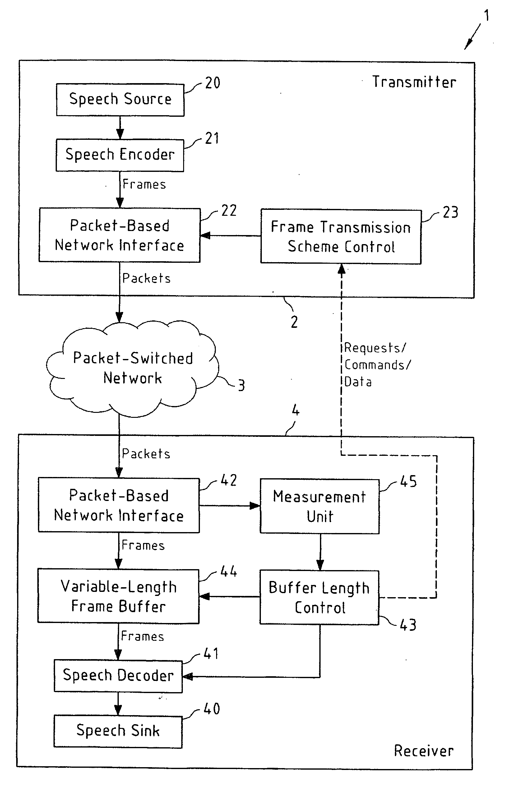
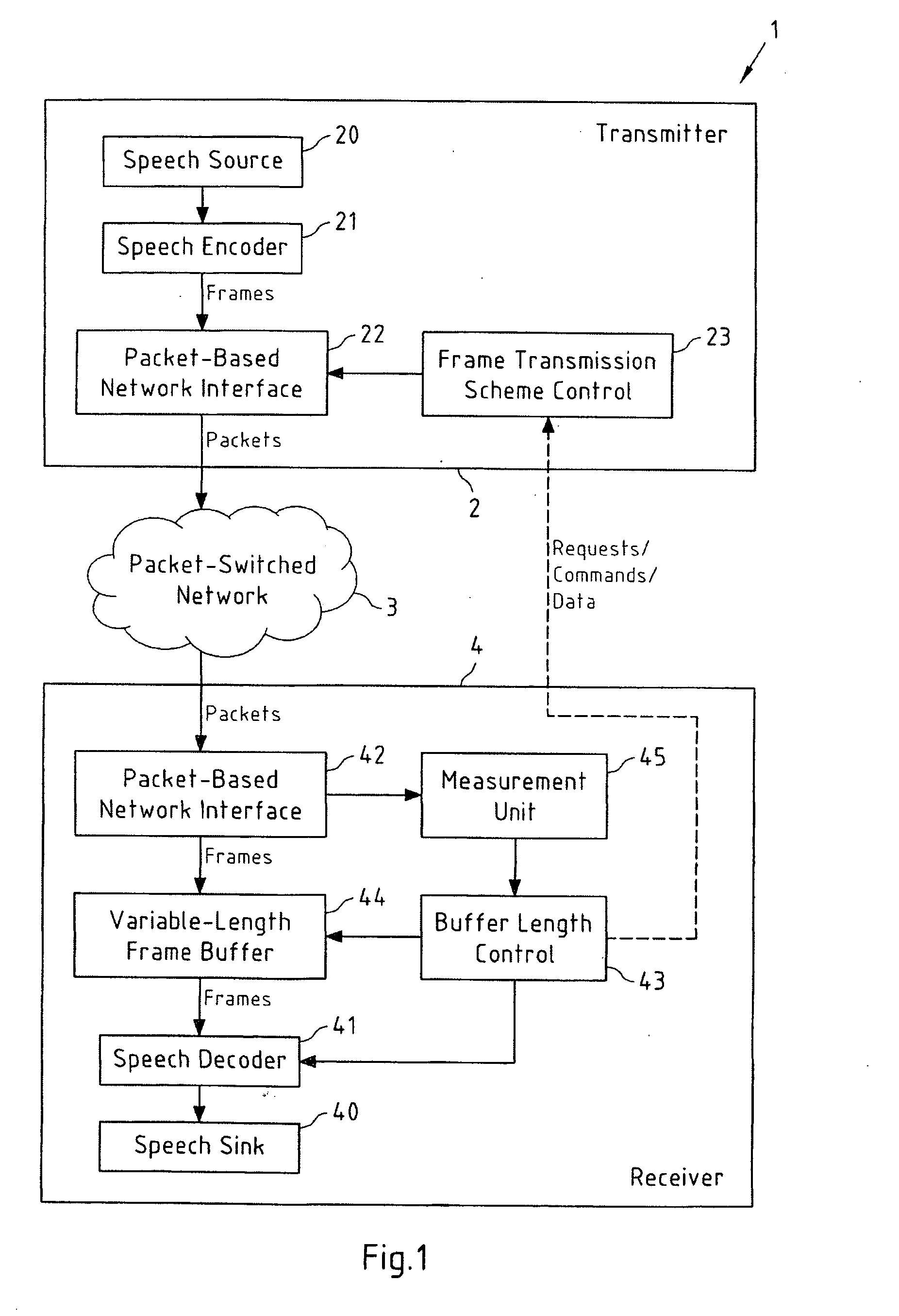
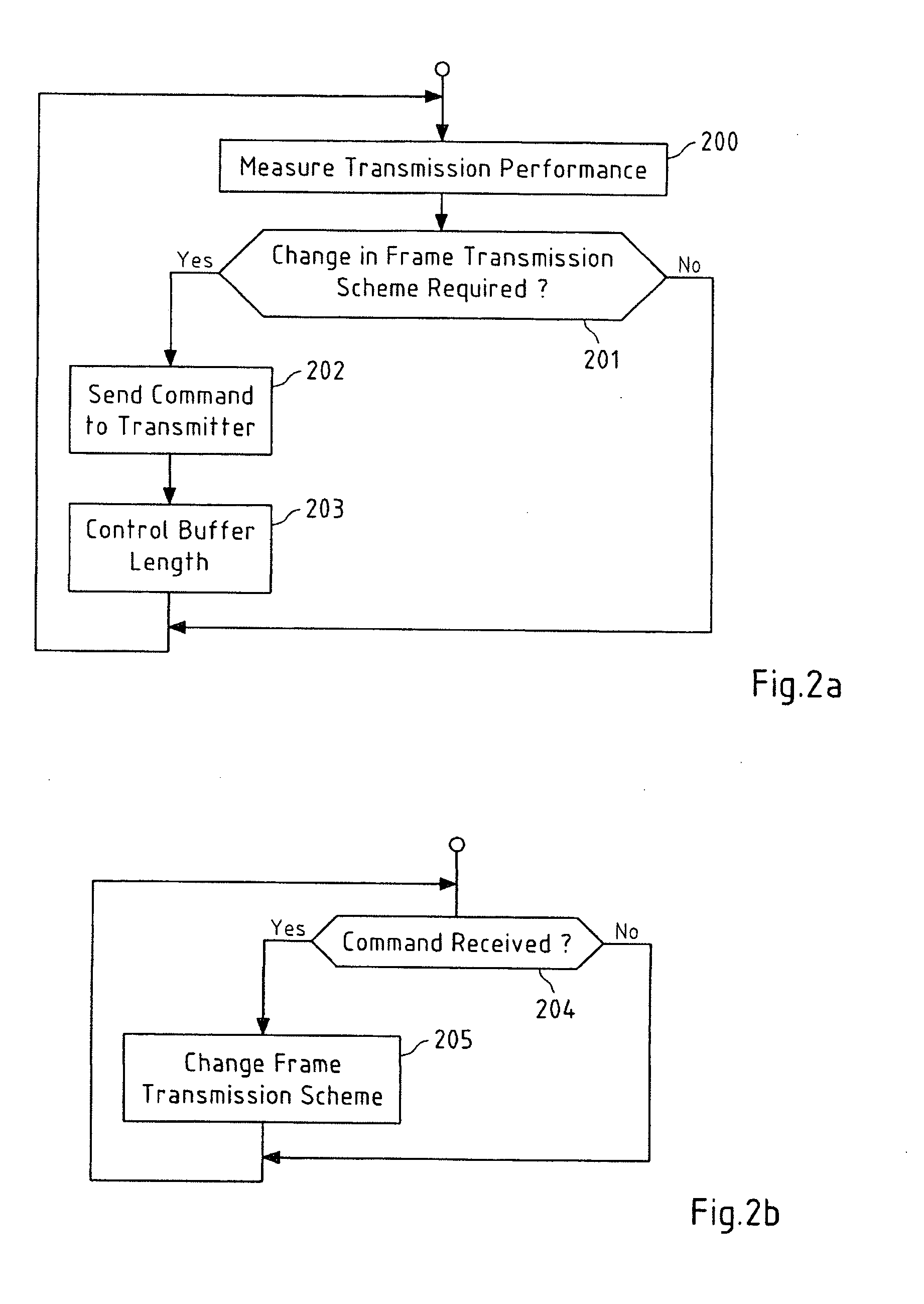
[0062] which is depicted in the flowcharts of FIGS. 2a and 2b, relating to the processing at receiver 4 and transmitter 2 (see FIG. 1), respectively, receiver 4 measures the transmission performance of the packet-switched network 3 in a step 200, for instance in terms of packet loss rate and jitter. Based on these measurements, receiver 4 decides, in a step 201, if a change in the frame transmission scheme at transmitter 2 is required. If this is the case, a command for a change in the frame transmission scheme is sent to transmitter 2 in a step 202. This command may for instance contain control information related for example to the desired frame transmission scheme, the number of redundant frames in frame redundancy transmission or the number of frames in frame aggregation transmission, to name but a few. Said command may for instance be a media adaptation command that further includes control information related to the codec mode (e.g. AMR / AMR-WB). The transmission of this comman...

second embodiment

[0064] which is depicted in the flowcharts of FIGS. 3a and 3b, relating to the processing at receiver 4 and transmitter 2 (see FIG. 1), respectively, receiver 4 once again measures the transmission performance of the packet-switched network 3 in a step 300. Based on these measurements, receiver 4 decides, in a step 301, if a change in the frame transmission scheme at transmitter 2 is required. However, instead of sending a command to transmitter 2, as it was the case in step 202 of the flowchart in FIG. 2a, buffer length control unit 43 now sends a request to change the frame transmission scheme to frame transmission scheme control unit 23 of transmitter 2 in a step 302. This request may contain control information as already described above with respect to the previous embodiment. Said request may for instance be a media adaptation request that further includes control information related to the codec mode (e.g. AMR / AMR-WB). In contrast to the command, the request leaves transmitte...

third embodiment

[0067] which is depicted in the flowcharts of FIGS. 4a and 4b, relating to the processing at receiver 4 and transmitter 2 (see FIG. 1), respectively, receiver 4 once again measures the transmission performance of the packet-switched network 3 in a step 400. In a step 401, the measured data is directly transmitted to transmitter 2, for instance in the form of RTCP receiver reports. This may be performed by the buffer length control unit 43 (as illustrated by the dashed line in FIG. 1), or by the measurement unit 45 itself. In a step 402, the buffer length control unit 43 nevertheless determines if a change in the frame transmission scheme is required or not, and, if this should be the case, controls the length of frame buffer 44 accordingly in a step 403. The flowchart then returns to step 400. The rationale behind this approach is that it is assumed that both transmitter 2 and receiver 4 use the same algorithm or a similar algorithm for determining whether a change in the frame tran...


PUM


Abstract

This invention relates to a method, a computer program product, apparatuses and a system for controlling a length of a frame buffer. The frame buffer is comprised in a receiver and buffers frames that are transmitted by a transmitter according to a frame transmission scheme and received at the receiver. The length of the frame buffer is controlled under consideration of a change in the frame transmission scheme.

Description

FIELD OF THE INVENTION[0001]This invention relates to a method, a computer program product, apparatuses and a system for controlling a length of a frame buffer.BACKGROUND OF THE INVENTION[0002]Controlling a length of a frame buffer (corresponding to the control of the buffering time) is for instance of technical interest in the context of packet-switched transmission of speech data.[0003]International publication WO 2006 / 044696 A1 discloses systems and methods for such a controlling of the length of a frame buffer. Therein, a receiver-side de-jitter buffer, which adds delay to received packets, adaptively adjusts its size based upon the detected air link characteristic, such that the de-jitter buffer is appropriately sized for anticipated data packets before they are received at the subscriber station.[0004]A particular application area of packet-switched transmission of speech data are Voice over Internet Protocol (VoIP) systems. The packet-switched network transmission protocols t...

Claims


Application Information

Patent Timeline
Patent Type & Authority Applications(United States)
IPC IPC(8): H04L12/56H04J3/22
CPCH04L47/10H04L47/36H04L47/30H04L47/26H04L47/267
Inventor OJALA, PASILAKANIEMI, ARI
Owner NOKIA CORP
Why Eureka
Try Eureka