Miniature non-directional microphone

Inactive Publication Date: 2008-05-01
THE RES FOUND OF STATE UNIV OF NEW YORK
View PDF6 Cites 6 Cited by
  • Summary
  • Abstract
  • Description
  • Claims
  • Application Information

AI Technical Summary

Benefits of technology

[0010]In accordance with a preferred embodiment, the present invention provides a tiny microphone diaphragm that is dramatically less stiff than what can be achieved with previous approaches. Therefore, the responsivity is increased.
[0011]A preferred embodiment in accordance with the present invention avoids imposing a large force between the diaphragm and the backplate due to a sensing voltage, and employs a different transduction approach, which does not require mechanical stiffness of the out-of-plane motion of the diaphragm to avoid collapse. Preferably, a significant electrostatic force component from the sensing voltage is disposed in the plane of the diaphragm, and thus has a lower tendency to displace the diaphragm.
[0012]The permitted use of a highly flexible diaphragm in accordance with preferred embodiments of the present invention causes the overall sensitivity to be less dependent on the diaphragm's stiffness and the size of the vent than that of prior approaches.
[0013]The microphone accordin

Problems solved by technology

In current design approaches, however, the small size of the microphone results in diminished sensitivity to sound, and in particular poor sensitivity to low frequencies.
As a result, great care must be taken in the design to maximize sensitivity, which generally adds to the complexity and cost of the device.
This increased stiffness with decreasing size is a fundamental challenge in the design of small microphones.
An additional challenge in the design of microphones comes from the use of a backplate electrode to achieve capacitive sensing.
However, great care must be taken to ensure that the resulting attractive force is n

Method used


Image

  • Miniature non-directional microphone
  • Miniature non-directional microphone
  • Miniature non-directional microphone

Examples


Embodiment Construction

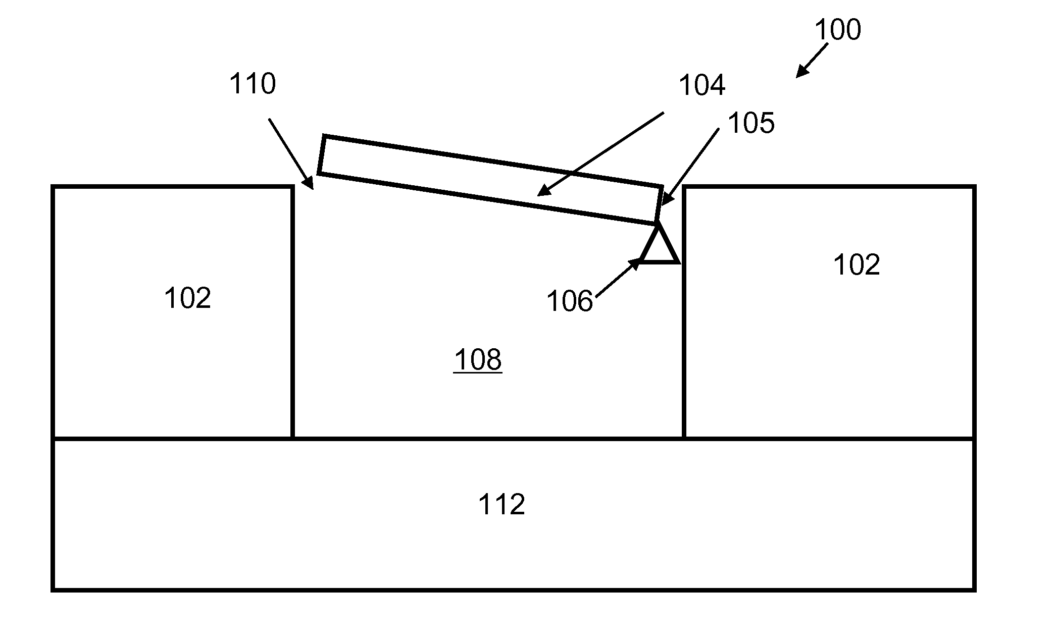
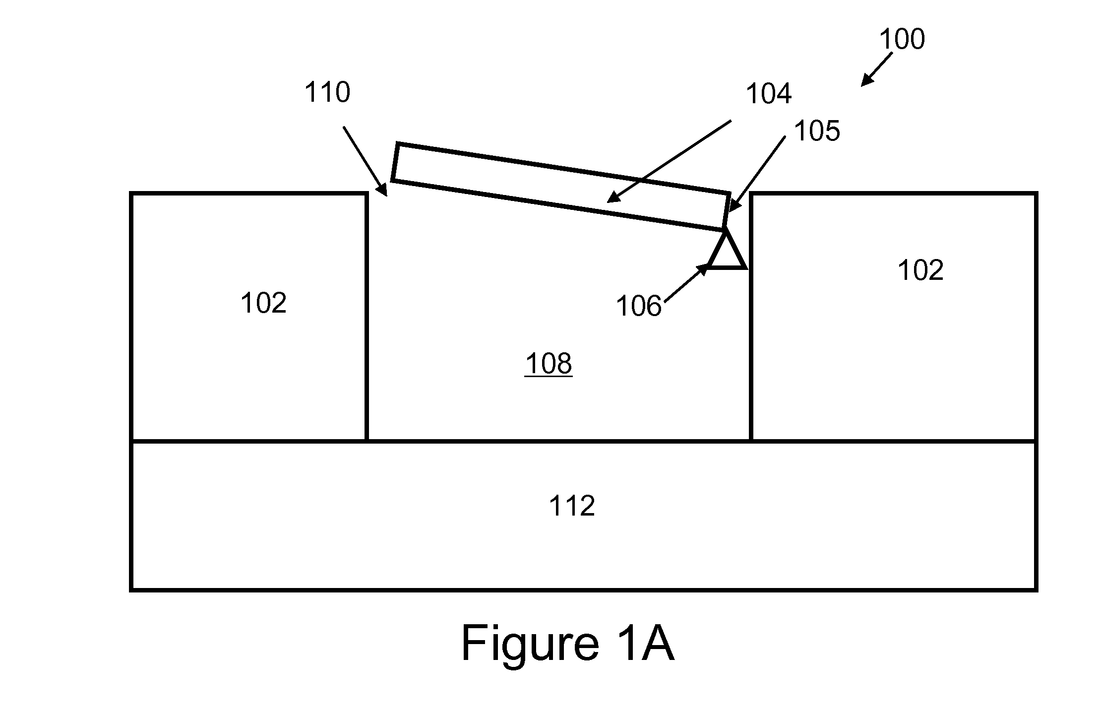
[0020]The motion of a diaphragm of a typical microphone results in a fluctuation in the net volume (at standardized temperature and pressure) of air in a region behind the diaphragm. The compression and expansion of the air in this region due to the diaphragm's motion results in a linear restoring force that effectively stiffens the diaphragm and reduces its response to sound. This stiffness acts in parallel with the mechanical stiffness of the diaphragm, which, in small microphones and particularly in silicon microphones, is normally much greater than the stiffness of the air in the back volume.

[0021]The present invention permits a diaphragm to be designed such that its mechanical stiffness is much less than that resulting from the compression of air or fluid in the back volume, even though the diaphragm is fabricated out of a very stiff material such as silicon.

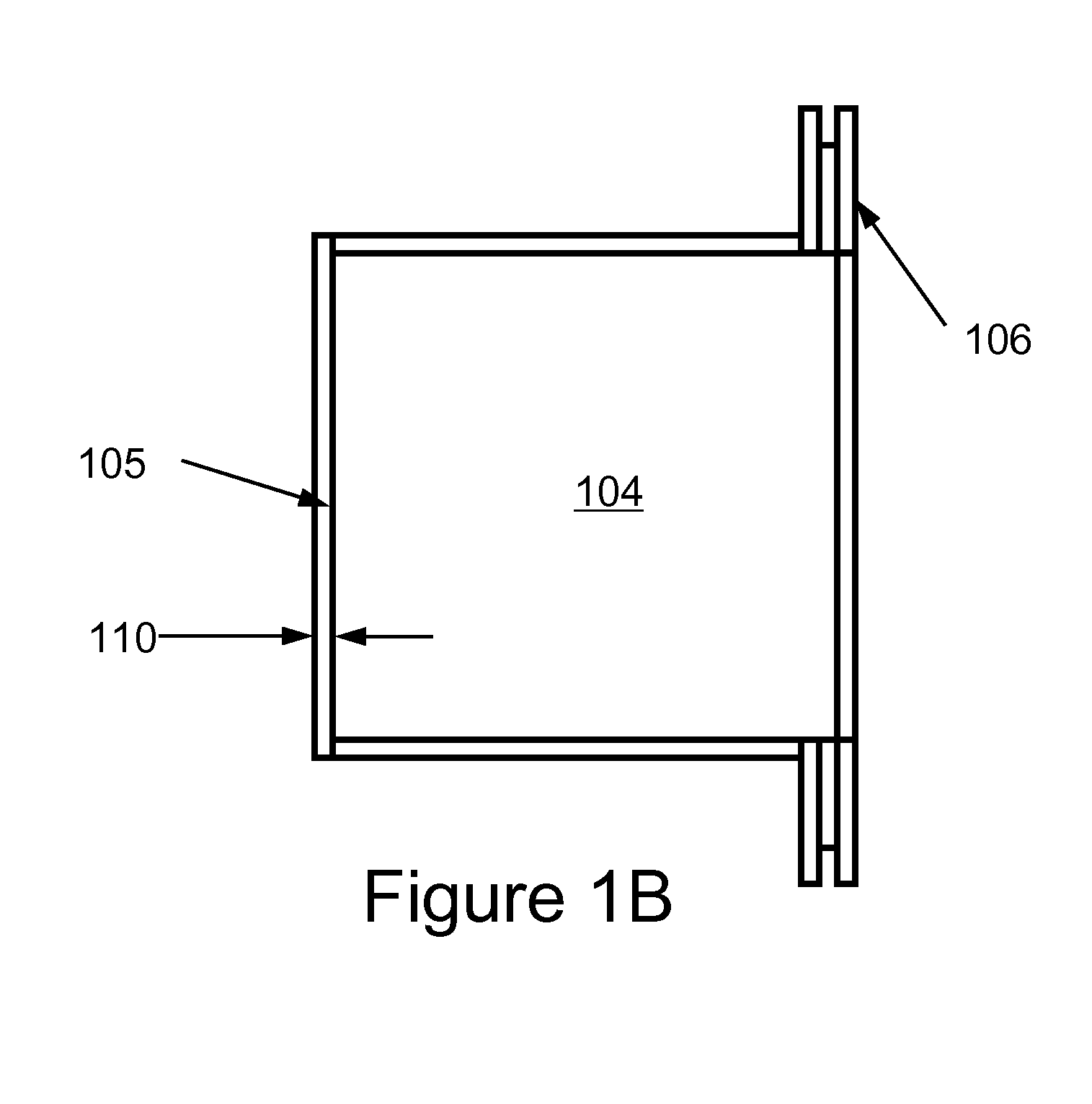
[0022]Unlike typical microphone diaphragms that are supported around their entire perimeter, the diaphragm according to a...


PUM


Abstract

A miniature microphone comprising a diaphragm compliantly suspended over an enclosed air volume having a vent port is provided, wherein an effective stiffness of the diaphragm with respect to displacement by acoustic vibrations is controlled principally by the enclosed air volume and the port. The microphone may be formed using silicon microfabrication techniques and has sensitivity to sound pressure substantially unrelated to the size of the diaphragm over a broad range of realistic sizes. The diaphragm is rotatively suspend for movement through an arc in response to acoustic vibrations, for example by beams or tabs, and has a surrounding perimeter slit separating the diaphragm from its support structure. The air volume behind the diaphragm provides a restoring spring force for the diaphragm. The microphone's sensitivity is related to the air volume, perimeter slit, and stiffness of the diaphragm and its mechanical supports, and not the area of the diaphragm.

Description

RELATED APPLICATIONS[0001]The present invention is related to co-pending U.S. patent application Ser. No. 10 / 689,189, for ROBUST DIAPHRAGM FOR AN ACOUSTIC DEVICE, filed Oct. 20, 2003, Ser. No. 11 / 198,370 for COMB SENSE MICROPHONE, filed Aug. 5, 2005, Ser. No. 11 / 335,137 for OPTICAL SENSING IN A DIRECTIONAL MEMS MICROPHONE, filed Jan. 19, 2006, and Ser. No. 11 / 343,564 for SURFACE MICROMACHINED MICROPHONE, filed Jan. 31, 2006, all of which are included herein in their entirety by reference.FUNDED RESEARCH[0002]This work is supported in part by Grant No. 1035968 from the National Institutes of Health. The Government may have certain rights in this invention.FIELD OF THE INVENTION[0003]The present invention relates to the field of miniature non-directional microphones, particular, to miniature microphones having high sensitivity and good low frequency response characteristics.BACKGROUND OF THE INVENTION[0004]Small microphones that can be manufactured with low cost are highly desirable c...

Claims


Application Information

Patent Timeline
IPC IPC(8): H04R11/04H04R17/02H04R9/08
CPCH04R23/006B81B3/0027H04R9/08H04R11/04H04R17/02H04R19/005H04R19/04H04R7/02
Inventor MILES, RONALD N.
Owner THE RES FOUND OF STATE UNIV OF NEW YORK
Why Eureka
Try Eureka