Correlation peak finding method for image correlation displacement sensing

Active Publication Date: 2008-05-01
MITUTOYO CORP
View PDF16 Cites 22 Cited by
  • Summary
  • Abstract
  • Description
  • Claims
  • Application Information

AI Technical Summary

Benefits of technology

[0007]A correlation function peak finding method for use in an image correlation displacement sensing system is provided. The method reduces the types of systematic sub-pixel errors outlined above. In accordance with one aspect of the invention, a windowing function and/or weighting factors are applied prior to, or as part of, f

Problems solved by technology

Certain systematic periodic sub-pixel errors arise when estimating the best correlation location or offset between a reference image and displaced images.
The systematic sub-pixel error arises because of the discrete sampling procedure that is inherent in the li

Method used


Image

  • Correlation peak finding method for image correlation displacement sensing
  • Correlation peak finding method for image correlation displacement sensing
  • Correlation peak finding method for image correlation displacement sensing

Examples


Embodiment Construction

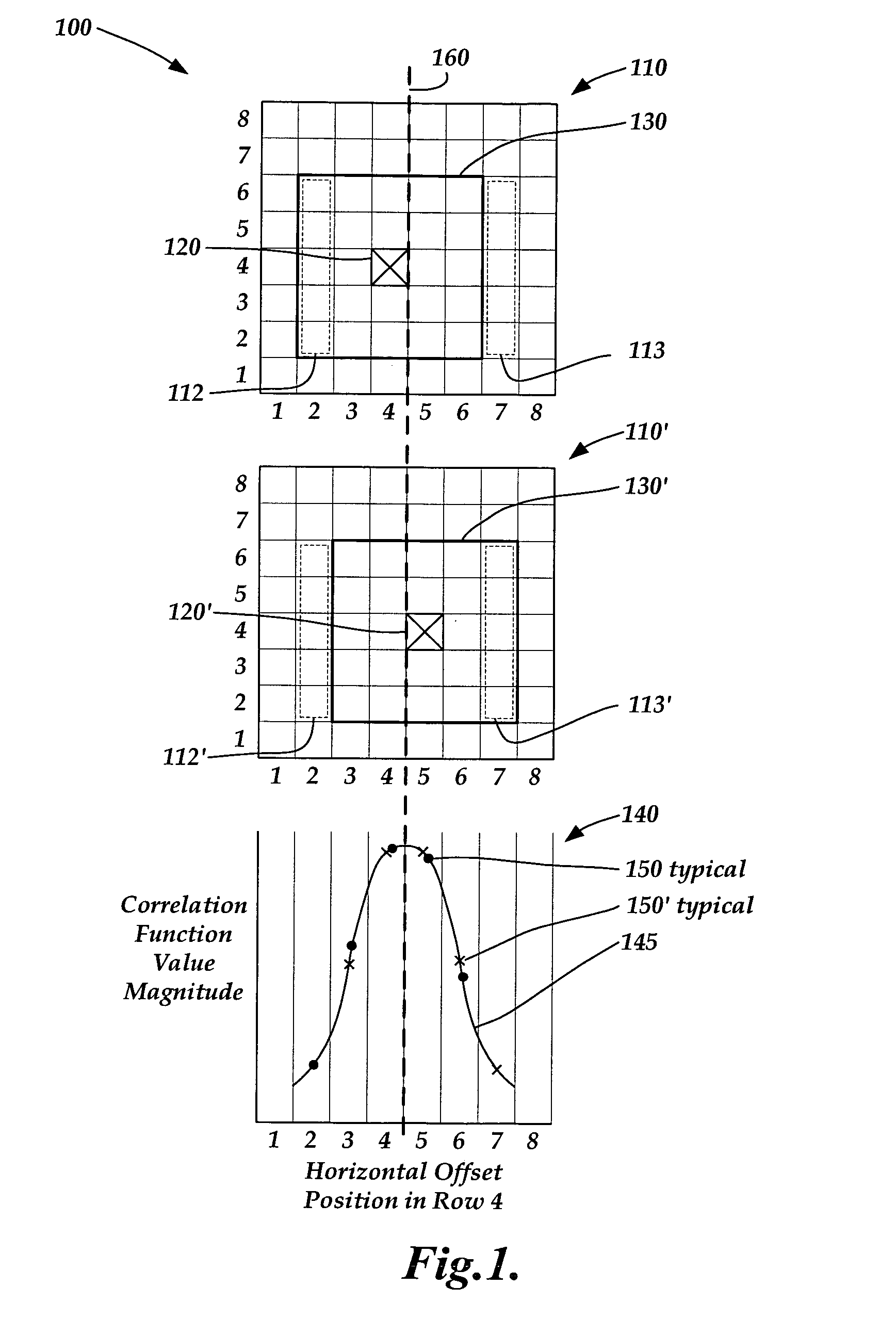
[0015]FIG. 1 shows a diagram 100 that illustrates one way of describing how periodic sub-pixel errors may arise when determining displacements by estimating correlation function peak locations using relatively few correlation function value points. The diagram 100 shows a first schematically illustrated 2D correlation function value point pseudo-image 110 corresponding to a first displacement between a reference image of an object and a first subsequent image of the object. Also shown is a second schematically illustrated 2D correlation function value point pseudo-image 110′ corresponding to a second displacement between the same reference image of an object and a second subsequent image of the object. Also shown is 1D correlation function value magnitude plot 140. The pseudo-images 110 and 100′, and the plot 140, are all aligned to a common reference frame along the horizontal direction in the FIG. 1, as described in greater detail below.

[0016]The schematic illustration of the pseu...


PUM


Abstract

A correlation function peak finding method for an image correlation displacement sensing system is provided. The method may include capturing a reference image and a displaced image, and searching for an initial peak correlation function value point (CFVP) with pixel-level resolution based on correlating the reference image and displaced images at a plurality of offset positions. Then a complete set of CFVPs may be determined at each offset position in an analysis region surrounding the initial peak CFVP. Then a preliminary correlation function peak location is estimated with sub-pixel resolution, based on CFVPs included in the analysis region. Finally, curve-fitting operations are performed to estimate a final correlation function peak location with sub-pixel accuracy, wherein the curve-fitting operations apply a windowing function and/or a set of weighting factors that is/are located with sub-pixel resolution based on the preliminary sub-pixel correlation function peak location.

Description

FIELD OF THE INVENTION[0001]This invention is directed to determining object displacements using image correlation.BACKGROUND OF THE INVENTION[0002]Various known devices use images acquired by a sensor array, and correlation between images acquired by the sensor array, to determine deformations and / or displacements of an object. For example, one class of such devices is described in U.S. Pat. No. 6,873,422 (the '422 patent), U.S. Pat. No. 6,990,254 (the '254 patent), U.S. Pat. No. 6,996,291 (the '291 patent), and U.S. Pat. No. 7,065,258 (the '258) patent, all to Nahum, each of which is hereby incorporated by reference in its entirety. In general, in such devices, prior to displacing or deforming the object, a first or reference image arising from the object is captured and stored. Then, after displacing or deforming the object, a second or subsequent image arising from the object is captured and stored. The first and second images are then quantitatively compared, e.g. by correlatio...

Claims


Application Information

Patent Timeline
IPC IPC(8): G06K9/64
CPCG06T7/0026G06F17/153G06T7/32
Inventor BRYLL, ROBERT KAMILJONES, BENJAMIN KEITHMASRELIEZ, KARL GUSTAV
Owner MITUTOYO CORP
Why Eureka
Try Eureka