Interventional catheters having cutter assemblies and differential cutting surfaces for use in such assemblies

a technology of cutters and assemblies, which is applied in the field of interventional catheters, can solve the problems of affecting the safety and reliability of the system, diamond grit particles, and diamond grit particles not operating as differential cutters, and achieve the effect of clearing an even larger volume of occlusive materials

Active Publication Date: 2008-05-01
BOSTON SCI LTD
View PDF25 Cites 211 Cited by
  • Summary
  • Abstract
  • Description
  • Claims
  • Application Information

AI Technical Summary

Benefits of technology

[0021] The cutter assembly may comprise one or more cutters or cutting surfaces and one or more distinct types of cutter elements. For example, a dual cutter configuration incorporates a fixed diameter cutter and an adjustable diameter cutter in combination. Dual cutter assembly configurations are described in the prior art publications incorporated herein by reference and may present two different material removal profiles in two different operational modes. In one mode, the cutter assembly is rotated and advanced to remove occlusive material in an initial “pilot pass” in which the fixed diameter cutter is the primary cutter, and the adjustable diameter cutter is in a smaller diameter condition. Following one or more pilot passes, the adjustab...

Problems solved by technology

Despite the many and varied approaches to material removal systems, many challenges remain in providing systems for removing material from a lumen, such as a blood vessel, safely and reliably and without causing complications.
The safety and reliability of the system is manifestly critical.
Diamond grit particles, however, do not operate as differential cutters except in their smallest embodiment because, depending on their orientation on the cutting surface, their exposed surfaces form random cant angles producing different cutting characteristics at different points of contact with tissue.
Relatively coarse diamond grit can act as a differential cutter because of the ratios of diamond size and population to tissue flexibility, but typically is more likely to damage elastic, healthy tissue such as blood vessel walls.
Relatively fine diamond grit has slow material removal rates, requiring the use of higher rotational...

Method used


Image

  • Interventional catheters having cutter assemblies and differential cutting surfaces for use in such assemblies
  • Interventional catheters having cutter assemblies and differential cutting surfaces for use in such assemblies
  • Interventional catheters having cutter assemblies and differential cutting surfaces for use in such assemblies

Examples


Embodiment Construction

[0037] Certain preferred embodiments are described herein with reference to a material removal device having a rotational cutting head. It will be appreciated that this device embodiment is being described as illustrative and that the inventions and features disclosed herein are applicable to interventional catheters having different types of operating heads.

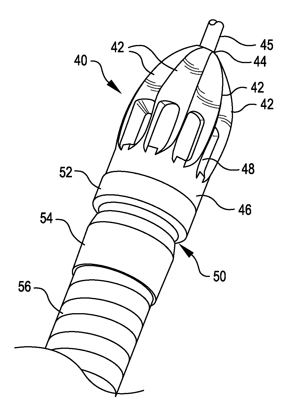
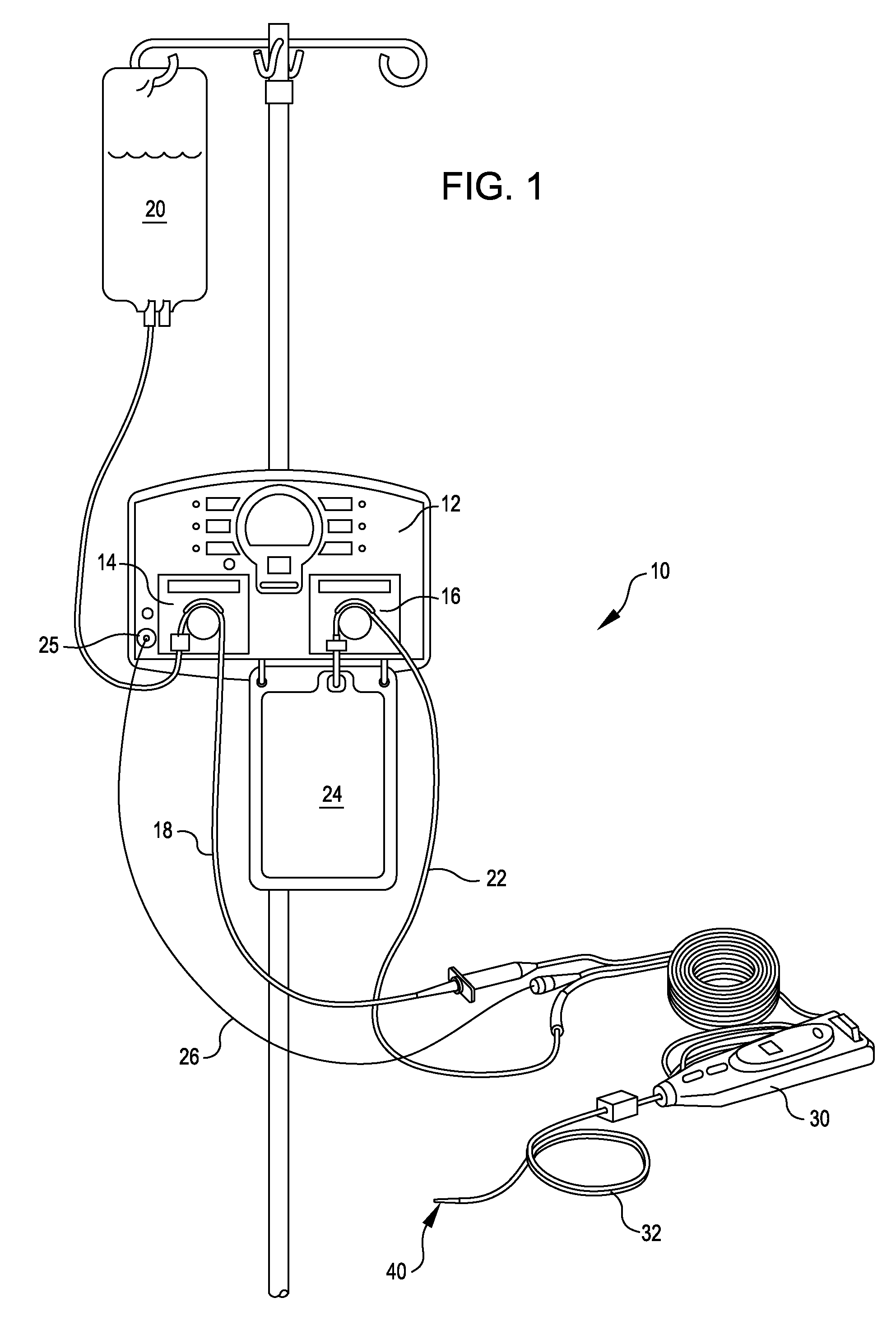
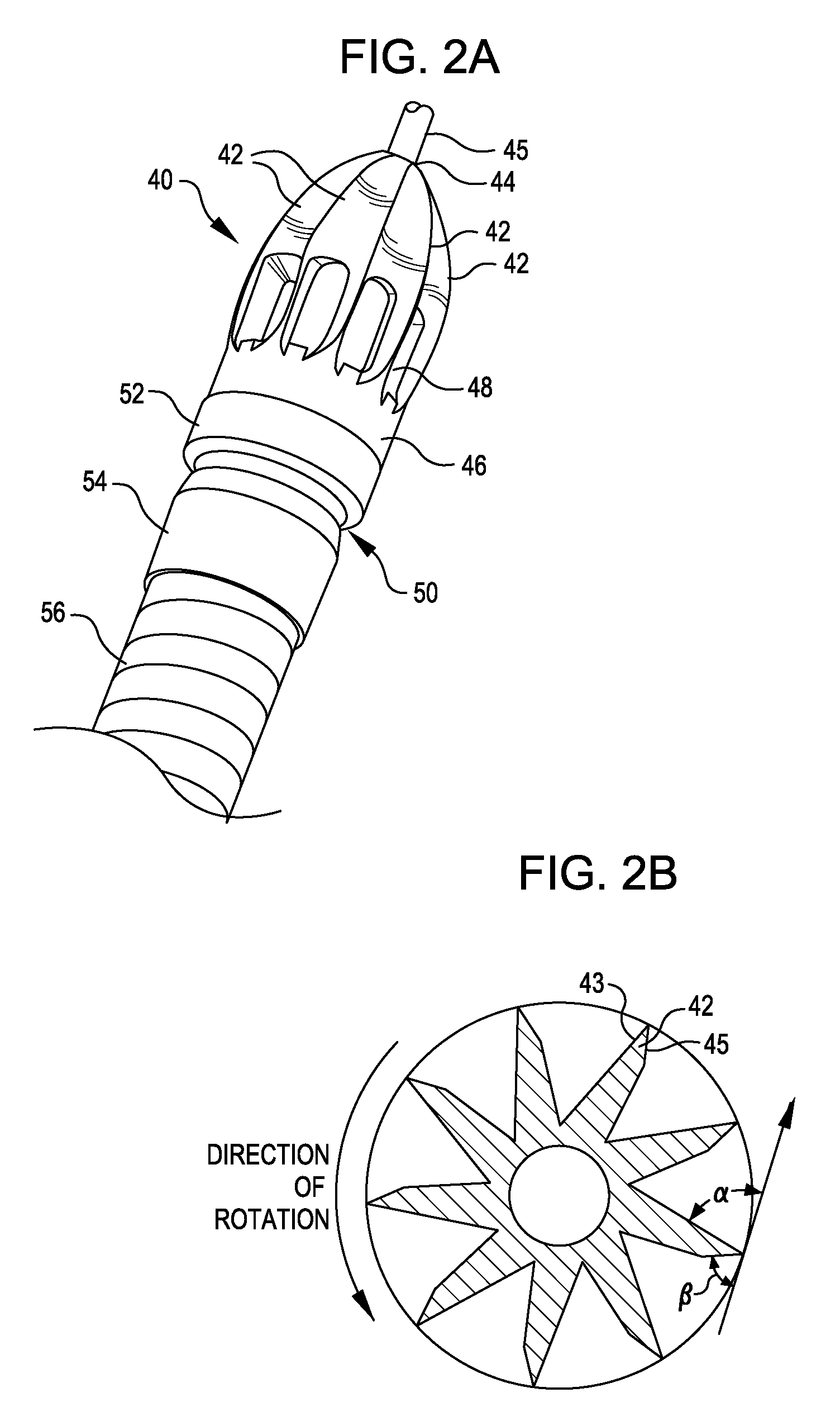
[0038]FIG. 1 illustrates an exemplary embodiment of an interventional catheter assembly 10 comprising console unit 12, controller 30, and catheter system 32 having a rotatable operating head 40 located at or in proximity to the distal end of the catheter system and incorporating one or more cutter assemblies. Controller 30 may be used to manipulate (e.g. advance and / or rotate) the catheter system 32 and operating head 40, or alternative controls may be provided. The configuration of the operating head and cutter assemblies will be described below with reference to FIGS. 2-7.

[0039] Console unit 12 may incorporate an infusion pu...


PUM


Abstract

A rotatable operating head for removal of obstructive material from a target site in a body lumen or cavity is operably connected to a rotatable, translatable drive shaft, that is driven by a drive motor and received through an elongated catheter. The operating head includes a plurality of differential cutting blades, with at least one of the cutting blades being a stepped blade, the stepped blade comprising a raised cutting surface positioned adjacent, or in proximity to, a shoulder region.

Description

REFERENCE TO PRIORITY APPLICATIONS [0001] This application claims priority to U.S. provisional patent application Nos. 60 / 894,173 filed Mar. 9, 2007, and 60 / 828,209 filed Oct. 4, 2006. The disclosures of these priority applications are incorporated by reference herein in their entireties.FIELD OF THE INVENTION [0002] The present invention relates to methods and systems for removing material, such as obstructions and partial obstructions, from an internal lumen or cavity of a mammalian subject, such as a blood vessel. More particularly, the present invention relates to interventional catheters having rotating operating heads incorporating blade structures for removing obstructions and partial obstructions from a lumen or cavity. BACKGROUND OF THE INVENTION [0003] Removal of disease such as atherosclerotic plaque, thrombus and other types of obstructions and partial obstructions from internal body lumens or cavities using advanceable, rotating operating heads is a well-established int...

Claims


Application Information

Patent Timeline
IPC IPC(8): A61B17/32
CPCA61B17/3207A61B17/320758A61B2017/320775A61B2217/005A61B2217/007A61M25/09A61B1/05A61B8/12A61B8/445A61M1/0084A61B1/00087A61M1/84A61M1/71A61M1/80A61B17/22A61B17/32A61M25/00A61B2017/22079A61M5/142A61M5/16831A61M25/0082A61B17/32002A61B17/320725A61B2017/320004A61B2017/320032
Inventor WULFMAN, EDWARD I.TORRANCE, CASEY
Owner BOSTON SCI LTD
Why Eureka
Try Eureka