Negative pressure control apparatus for vehicle breaking operation

Inactive Publication Date: 2008-05-01
DENSO CORP +1
View PDF15 Cites 39 Cited by
  • Summary
  • Abstract
  • Description
  • Claims
  • Application Information

AI Technical Summary

Benefits of technology

[0008] According to the control apparatus for the braking negative pressure, the negative pressure control valve is operated in accordance with the operational condition of the engine, so that the braking negative pressure can be decreased to a target negative pressure (increase of the negative pressure) or the decreased negative pressure can be maintained. As a result, stable braking performance can be assured.
[0018] According to a still further feature of the present invention, it is more preferable, to decrease the first predetermined flow amount more, as a rotational speed of the engine is lower and / or an engine load is smaller.
[0023] According to a still further feature of the present invention, it is more preferable, to increase the fourth predetermined flow amount more, as a rotational speed of the engine is higher and / or an engine load is larger.

Problems solved by technology

Therefore, it is disadvantageous in the multiple-valve type throttle system, in that it is not easy to obtain the negative pressure for the braking operation.
As above, in the multiple-valve type throttle system, it is a problem that the negative pressure for the braking operation can not be easily obtained.

Method used


Image

  • Negative pressure control apparatus for vehicle breaking operation
  • Negative pressure control apparatus for vehicle breaking operation
  • Negative pressure control apparatus for vehicle breaking operation

Examples


first embodiment

[0046] A first embodiment of the present invention will be explained with reference to FIGS. 1 to 14.

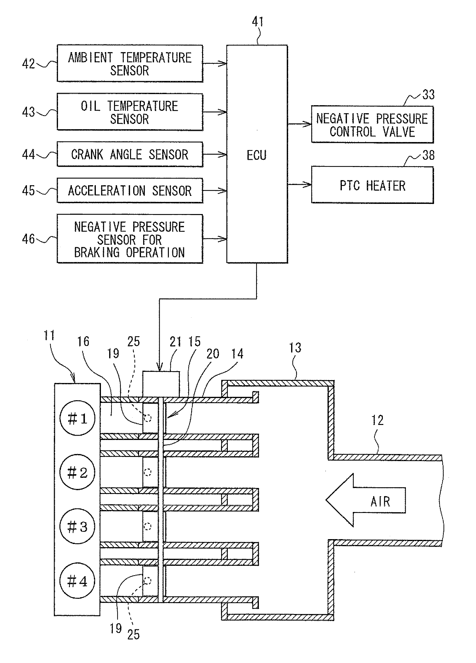
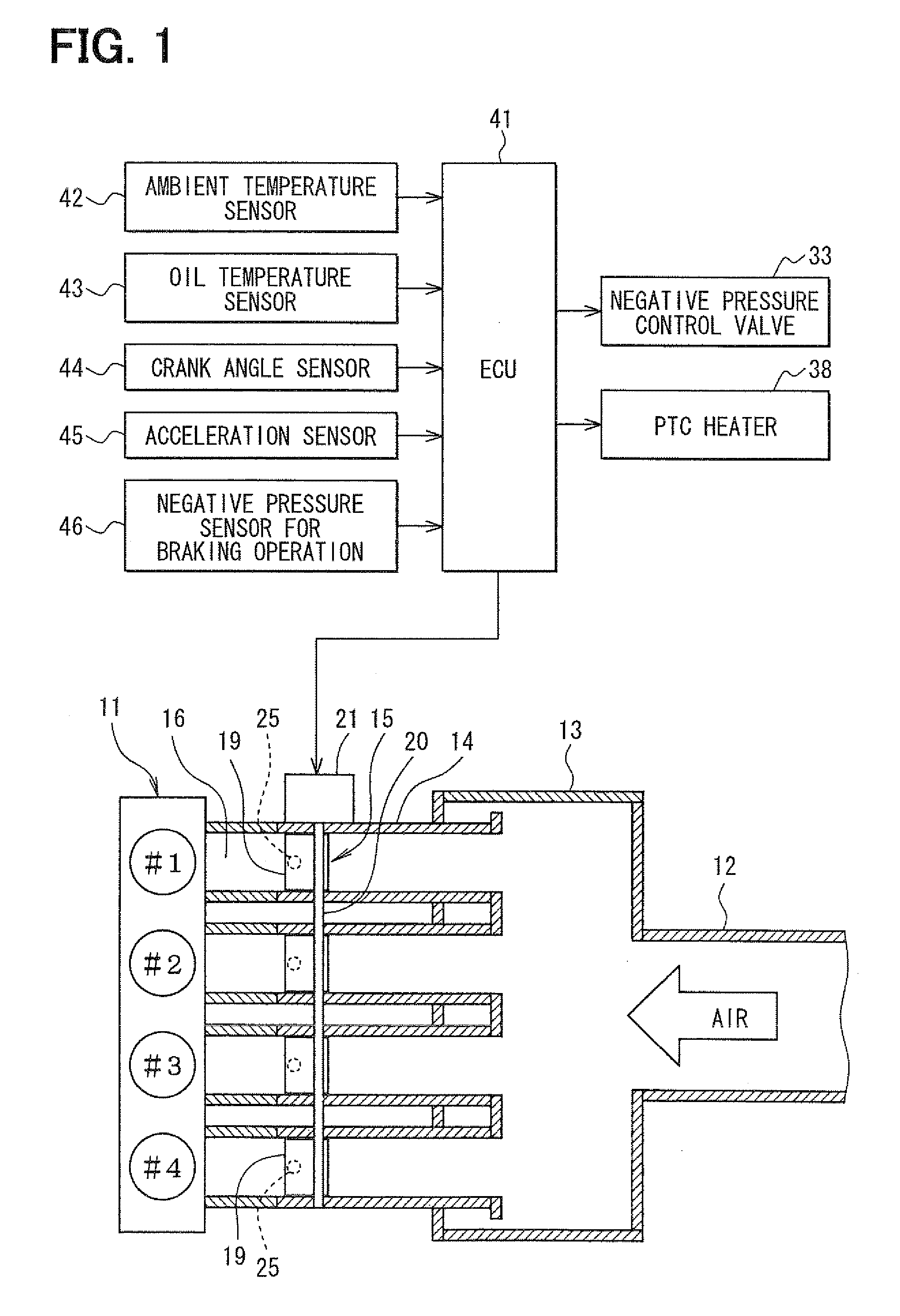
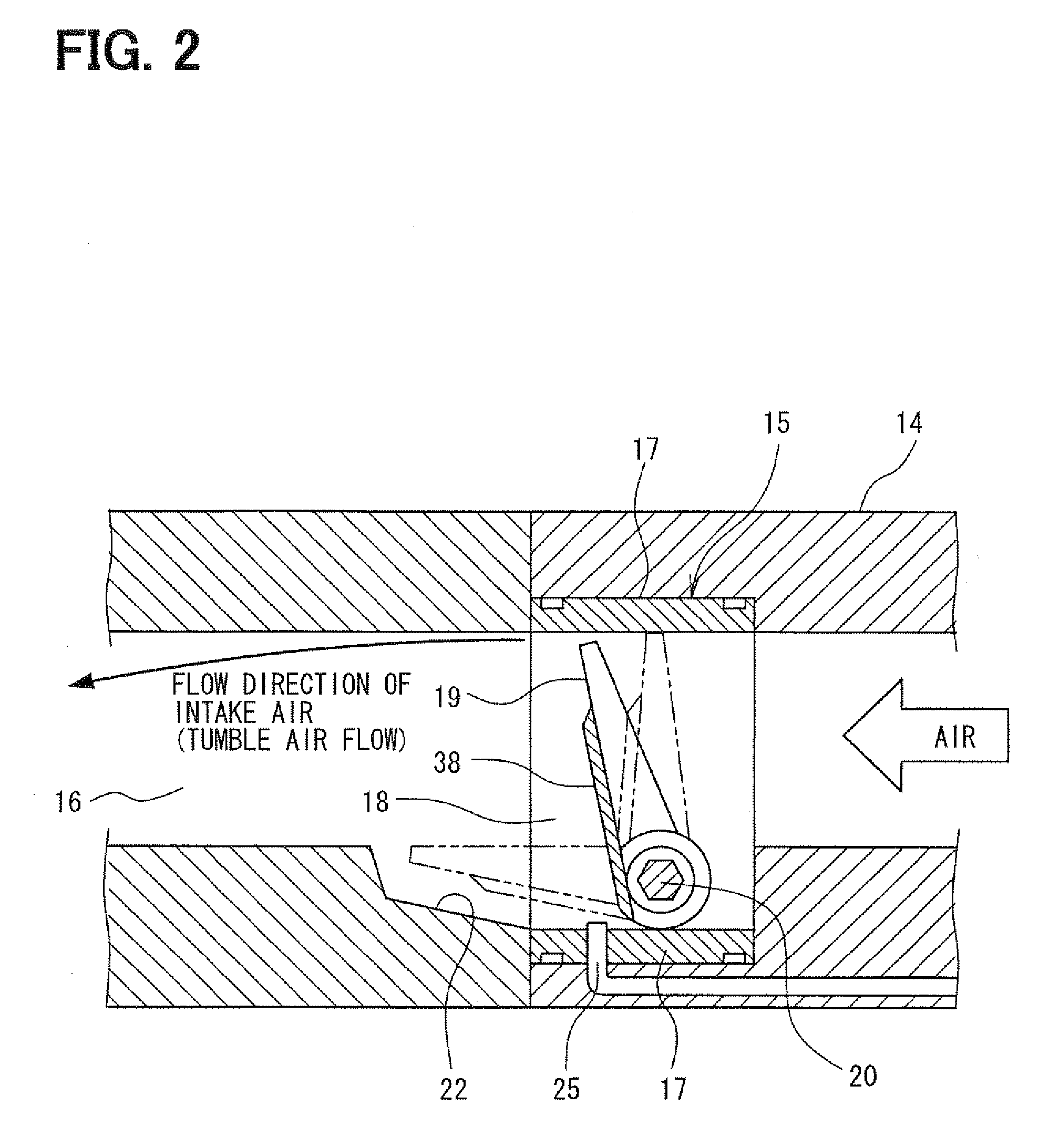
[0047] A general structure of an engine intake system will be explained with reference to FIG. 1. An internal combustion engine 11, for example, an in-line four cylinder engine, has four cylinders, that are first to fourth cylinders #1 to #4. An air flow meter (not shown) is provided in an intake pipe 12 (a main intake air passage) of the engine 11, in order to detect intake air amount. A surge tank 13 is provided at a downstream side of the air flow meter. Intake manifolds (branched intake air passages) 14 are connected to the surge tank 13, to supply the intake air into respective cylinders of the engine 11. Throttle valve units 15 are provided in each of the intake manifolds 14, to control the intake air amount to be supplied to the respective cylinders. Fuel injection valves (not shown) are provided adjacent to an intake port 16 of the respective cylinders, to inject fuel into t...

second embodiment

[0118] The above first embodiment shows an example, in which the air ejector 27 is used. It is not necessary to positively use the PCV gas as the driving gas for the air ejector 27, in such an engine in which the amount of the PCV gas is small, or in such an arrangement in which the PCV gas is discharged into the intake pipe at the upstream side of the throttle valve 19 (adjacent to a fully closed position of the throttle valve 19).

[0119] According to such an arrangement, the air ejector 27 may be eliminated, but a structure according to a second embodiment shown in FIGS. 15 to 20 may be used. The second embodiment will be explained below.

[0120] According to the second embodiment, as shown in FIG. 15, is the negative pressure passage 36 of the brake booster 35 is connected to the negative pressure pipe 26, to which the communication passages 25 for the respective cylinders are converged, via a negative pressure control valve 51. A check valve 52 is provided in each of the communic...

third embodiment

[0141] In the above explained first and second embodiments, the cantilever type throttle valve 19 is used, wherein the throttle valve 19 has the shaft 20 at the lower side of the throttle valve unit is. According to the third embodiment shown in FIG. 21, however, a throttle valve 63 of a butterfly-valve type is used, wherein the throttle valve 63 has a shaft 62 at a center of a throttle valve unit 61.

[0142] In the third embodiment, a bore 66 of a spherical surface is formed at a lower surface of an air passage 65 of a housing 64 for the throttle valve unit 61, wherein the shape of the bore 66 (the spherical surface) is so formed to correspond to a shape of a lower end of the throttle valve 63. Accordingly, a space (a gap) between the lower end of the throttle valve 63 and the lower surface of the air passage 65 is closed by the bore 66, when the throttle valve 63 is in a predetermined opening degree (for example, 20 degrees) from its fully closed position. As a result, an air flow ...


PUM


Abstract

A communication passage for generating braking negative pressure is connected to an air passage for respective cylinders at a downstream side of a throttle valve. An air ejector is provided in a negative pressure pipe, to which communication passages for the respective cylinders are converged. A negative pressure passage for a brake booster is connected to the air ejector at a side of suction gas via a check valve. A passage for PCV gas and an intake air branched passage for bifurcating a part of the intake air from a surge tank at an upstream side of the throttle valve are connected to a driving gas side of the air ejector, wherein a negative pressure control valve is provided in the intake air branched passage. The PCV gas and the part of the intake air are forced to flow into the driving gas side of the air ejector, so that the air ejector functions as a vacuum pump. As a result, the braking negative pressure for the brake booster can be surely reduced to a target negative pressure.

Description

CROSS REFERENCE TO RELATED APPLICATION [0001] This application is based on Japanese Patent Application No. 2006-292062 filed on Oct. 27, 2006, the disclosure of which is incorporated herein by reference. FIELD OF THE INVENTION [0002] The present invention relates to a negative pressure control apparatus for a vehicle braking operation, in which a throttle valve for controlling intake air amount is provided in each of branched intake air passages for supplying the intake air to respective engine cylinders. BACKGROUND OF THE INVENTION [0003] Recently, as disclosed in Japanese Patent Publication No. 2005-344606, throttle valves are provided in branched intake air passages (intake manifolds) for respective cylinders of an engine, so as to respectively control the intake air amount. In addition, a communication chamber is provided to communicate the intake air passages with each other at respective downstream sides of the throttle valves. A nipple for negative pressure is provided at the...

Claims


Application Information

Patent Timeline
IPC IPC(8): B60T8/17B60T17/00F02B31/00F02D9/02F02D9/10F02M35/10F02M35/104
CPCB60T17/02F02M35/10229B60T17/04
Inventor SUZUKI, HIDEKIHAYASHI, KAZUHIROOTSUBO, MAKOTO
Owner DENSO CORP
Why Eureka
Try Eureka