Navigation system

a navigation system and receiver technology, applied in navigation instruments, transmission monitoring, instruments, etc., can solve the problems of weak signals, high cost of making and operating, and the use of gps at a relatively slow update rate, so as to achieve fast calculation of the location of the target, high accuracy in determining the location, and the effect of fast update ra

Inactive Publication Date: 2008-05-01
HAILO TECH LLC +1
View PDF86 Cites 44 Cited by
  • Summary
  • Abstract
  • Description
  • Claims
  • Application Information

AI Technical Summary

Benefits of technology

[0009] Overview. The ad hoc network discussed herein is a wireless radio network for determining a target location with high positioning accuracy and fast update rate. Such a network includes multiple base stations and at least one target unit, linked together with via high frequency ultra-wide bandwidth (UWB) wireless ranging and communication (RAC) transceivers and location schemes. The UWB RAC scheme ensures the desired accuracy in distance measurements and station identification. The location schemes employ fast direct closed-form solution for self-organizing local and global geographic (e.g. GPS) coordinate systems, and determining position of base stations and targets within the desired coordinate system.
[0014] Radio Penetration. The high frequency UWB spectrum also penetrates through objects including buildings, ground cover, weather elements, etc., more readily than other narrower bandwidth signals such as the GPS. This makes UWB advantageous for non-line-of-sights, and less susceptible to multipath and canopy problems.
[0015] Distributed Power Spread Spectrum. The bandwidth of UWB signals may range from approx 100 MHz to 10 GHz or more, which means that the power of the signals may be distributed almost evenly over the wide spread spectrum. The power spectral density of UWB signals has similar appearance to that of a random noise spectrum, and hence, often makes the UWB signals undetectable or ambiguious. UWB signals thus have desirable low probability interference and low probability detection characteristics.
[0016] UWB versus Narrowband Disturbance. The wide spread spectrum also makes it difficult for signals with lesser bandwidth to corrupt the UWB signals. This would be a desirable characteristics in the case of on deliberate jamming by a narrowband broadcast or disturbances.
[0017] Non-ambiguous Station Identification. The ad hoc network utilizes base stations equiped with UWB tranceivers. The base stations communicate with each other and uniquely identify themselves. The identity is encoded with transmitted UWB signals. A base station correlates a received signal with the base station that sent it, and thus aleviating any ambiguity about the identity of transmission sources.
[0022] Advantageous. The main advantagous of the Ad hoc network are 1) the ad hoc & mobile manner in which the base stations may be rapidly set up, 2) the high precision in determining the location of a target, 3) the fast update rate of the location calculations, 4) the high penetration property desirable for non line-of-sight applications, 5) the higher tolerance to radio disturbances and resistant to jamming.

Problems solved by technology

GPS has several draw backs including relatively weak signals that do not penetrate heavy ground cover and / or man made structures.
Furthermore, the weak signals require a sensitive receiver.
The accuracy of the GPS system relies heavily on the use of atomic clocks, which are expensive to make and operate.
In addition, GPS utilizes a relatively slow update rate; on the order of once per second, which makes it ill suited for use in autonomous navigation of a vehicle.
For an autonomous vehicle, significant changes in terrain may occur in this distance, making an update rate of once per second much too slow.
Known triangulation methods are also numerical in nature, meaning that no direct solution is available to find the location of the target.
The resolution and accuracy of the location determination suffers accordingly.
Further, using an open form solution in three dimensions is very difficult.

Method used


Image

  • Navigation system
  • Navigation system
  • Navigation system

Examples


Embodiment Construction

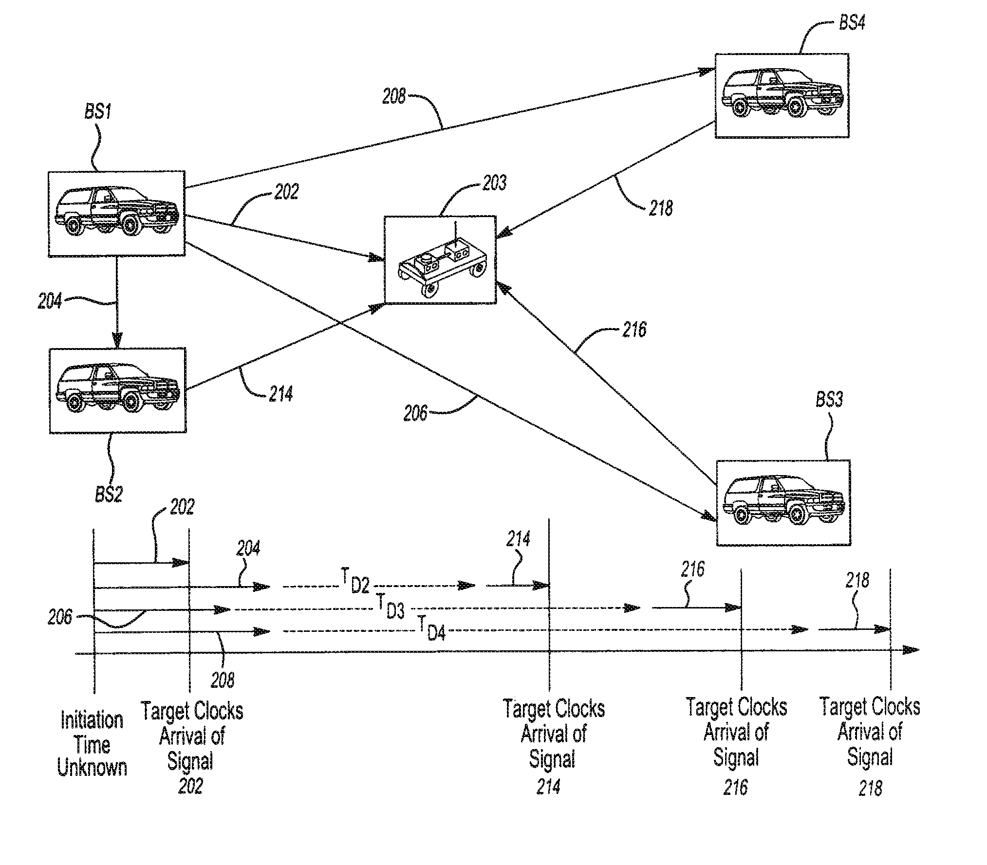
[0028] The method of the present invention includes initializing a network of at least three base stations to determine their relative location to each other in a coordinate system; measuring, at the target, the time of arrival of at least one signal from each of three base stations, and then calculating the location of the target on the coordinate system can be calculated directly.

[0029] The initializing step utilizes at least three base stations and preferably at least four base stations. The base stations are transceivers that are capable of both receiving and transmitting signals. One of the base stations may be designated as the master station, as necessary. The master designation is arbitrary and may be shuttled amongst the base stations. In a preferred embodiment, the master designation resides on a single base station until that base station becomes deactivated (e.g. the base stations is powered down, loses communication with or travels out of range of the other base statio...


PUM


Abstract

The present invention relates to a method of determining the location of a target. The method includes initializing a set of base stations to determine their location relative to each other. At the target, the time of arrival of at least one signal from each of the plurality of base stations Is measured. From this, the location of the target relative to the plurality of base stations may be directly calculated using a closed solution. In one embodiment, a time of arrival technique is used and in another embodiment a time difference of arrival technique is used. Preferably an ultra-wide band frequency is utilized.

Description

CLAIM OF PRIORITY [0001] The present application claims the benefit of provisional application Ser. No. 60 / 545,238, filed Feb. 17, 2004, Ser. No. 60 / 615,121, filed Oct. 1, 2004, and Ser. No. 60 / 637,276, filed Dec. 17, 2004, all of which are hereby incorporated by reference.FIELD OF THE INVENTION [0002] The present invention relates to the use of an ad hoc network during navigation and / or location. More particularly, the invention relates a system with three or more base stations, some of which are preferably mobile, that use explicit closed-form triangulation calculation to determine the location of a target. BACKGROUND OF THE INVENTION [0003] The Global Positioning System (GPS) is based on the fixed location base stations and the measurement of time-of-flight of accurately synchronized station signature transmissions. The base stations for the GPS are geo-stationary satellites and require atomic clocks for synchronization. [0004] GPS has several draw backs including relatively weak...

Claims


Application Information

Patent Timeline
Patent Type & Authority Applications(United States)
IPC IPC(8): G06F17/10H04B17/00G01S5/00G01S19/25G01S5/02G01S5/06G01S5/08G01S5/10G01S5/14H04W64/00
CPCG01S5/0284G01S5/0289G01S5/06H04W64/00G01S5/10G01S5/14G01S5/08
Inventor CHEOK, KA C.SMID, G. EDZKO
Owner HAILO TECH LLC
Why Eureka
Try Eureka