Fuel Leak Estimator

a technology of fuel leak estimator and fuel tank, which is applied in the direction of volume measurement apparatus/methods, liquid/fluent solid measurement, relative volume flow measurement, etc., can solve the problems of fuel tank leakage, improper maintenance, improper manufacture, etc., to facilitate detection, facilitate detection, effective and improved method of detecting fuel leakag

Inactive Publication Date: 2008-05-01
AIRBUS OPERATIONS LTD
View PDF8 Cites 12 Cited by
  • Summary
  • Abstract
  • Description
  • Claims
  • Application Information

AI Technical Summary

Benefits of technology

[0030]Certain embodiments of the present invention can advantageously facilitate detection of a persistent low flow-rate fuel leak, for example by means of effectively comparing the first parameter (a measure of the amount by which the quantity of fuel in the fuel store has reduced over a period of time) with the second parameter (a measure of the amount of fuel that has been measured as having flowed from the fuel store over that period of time). Preferably, a leak is deemed present if the effective discrepancy between the first and second parameters is greater than a preset threshold. Such a threshold may be necessary in view of inaccuracies in the measurements made. The measurement of the amount of fuel in the fuel store may for example be subject to measurement errors of the order of ±2% of the measured amount. Thus, even if the rate of fuel loss by means of the fuel leak is relatively low, certain embodiments of the present invention may enable detection of the leak, even though the rate of fuel loss may be small enough to remain undetected if the embodiments of the present invention relied solely on comparing the rate of the reduction in fuel in the fuel store as ascertained from successive measurements of the amount of fuel in the fuel store and the rate of fuel flow ascertained from the physical measurement(s) of fuel flow-rate(s). For example, consider a large aircraft, having a fuel capacity of 150 tonnes, wherein the rate of fuel used might, when cruising, be of the order of about 10 tonnes per hour. If soon after take-off fuel starts leaking at a constant rate of, say, 0.4 tonnes per hour (i.e. 4% of rate of fuel usage), then, over a period of several hours, the disparity between the amount of fuel measured as flowing out of the fuel store (by a fuel flow meter for example) and the amount by which the quantity of fuel in the store has reduced (as measured by one or more fuel probes for example) will become apparent, enabling the method to detect the low flow-rate leak.
[0031]Additionally or alternatively, certain embodiments of the present invention can also advantageously facilitate detection of a transitory high flow-rate fuel leak, for example by means of effectively comparing the third parameter (a measure of the rate at which the quantity of fuel in the fuel store is reducing at a first given instant) with the fourth parameter (the physical measurement of the rate of fuel flowing from the fuel store at the first given instant). Preferably, a leak is deemed present if the effective discrepancy between the third and fourth parameters is greater than a preset threshold. (This threshold would normally be different from the threshold mentioned above in relation to the fuel leak amount value.) In the case of the third parameter (the measure of the rate at which the quantity of fuel in the fuel store is reducing at a given instant), the errors in the third parameter (the errors being the difference between the real and measured values) may be relatively large as a result of the errors of differing sign and magnitude that may be present in the successive measurements of the amount of fuel in the fuel store that are used to ascertain the third parameter. For example, con

Problems solved by technology

There are several different possible causes for fuel leaks in an aircraft including foreign objects impacting against the fuel tank or associated system, and development of faults in the fuel tank and associated system resulting from fatigue and/or wear and tear.
More specifically, and by way of example, in an aircraft potential causes of fuel tank leaks include improper maintenance, improper manufacture, natural component ageing, uncontained engine rotor failure, battle damage, damage from impact of other foreign objects (for example, debris on the runway during take off or landing), system malfunctions or errors (for example, during to air to air refuelling, jettisoning fuel, de-fuelling or unintentional over-pressurising of the fuel tanks) and general component malfunction (for example, including the malfunction of components not directly associated with the fuel tank system which could subsequently cause damage to the fuel tank system).
Fuel may of course leak from the fuel tank itself or any part of the aircraft in which fuel is present.
By way of example, fuel may leak directly from a hole in the tank structure, from a hole in a fuel pipe or from a faulty seal between fuel pipes, or may leak from the surge tanks (the surge tanks accommodating overflow of fuel in the rest of the fuel system but only having a limited

Method used


Image

  • Fuel Leak Estimator
  • Fuel Leak Estimator
  • Fuel Leak Estimator

Examples


Embodiment Construction

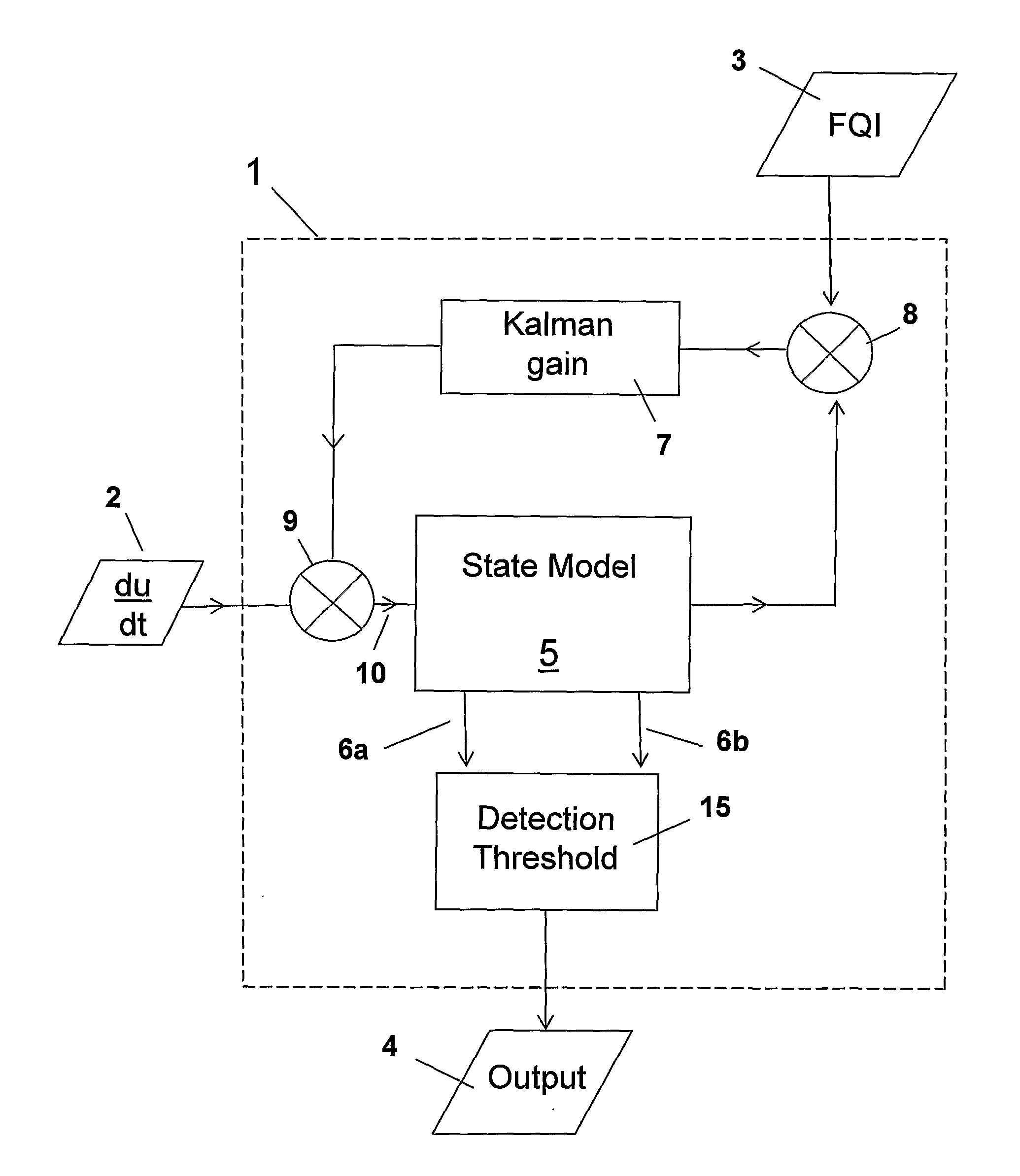
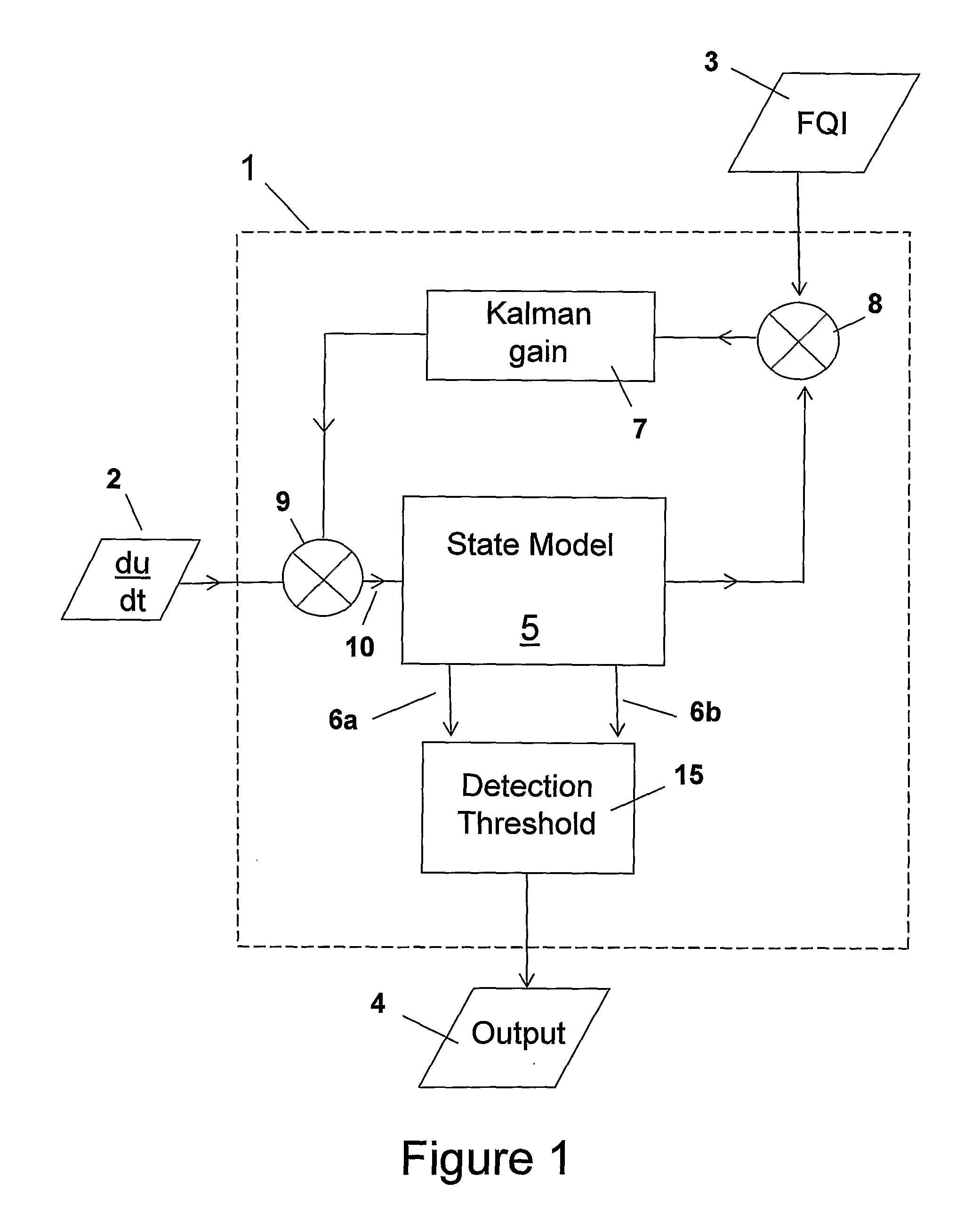
[0056]FIG. 1 shows an embodiment of the fuel flow monitoring system. In this particular case, the fuel flow monitoring system is provided to monitor the fuel levels in a single fuel tank in an aircraft, the fuel tank supplying fuel to a single engine. The fuel flow monitoring system comprises a processor 1, which is formed as part of the fuel system monitoring and management system of the aircraft. The processor is arranged to receive electronic input signals including a measured fuel flow input 2 and a measured fuel quantity indication (FQI) input 3. A fuel flow sensor is located in the fuel feed line from the aircraft fuel tank to the aircraft engine and measures the rate of fuel du / dt flowing along the feed line. The fuel flow sensor thus provides the fuel flow input 2. The fuel quantity input 3 is derived by a fuel quantity processor (not shown) from several different inputs from fuel level probes located at various locations in the aircraft fuel tank in consideration of the par...


PUM


Abstract

A method of detecting a fuel leak from a fuel store of an aircraft is described. In the described embodiment, a processor (1) receives inputs (2, 3) relating to the amount of fuel in the fuel store and to the rate of fuel used by the aircraft, both inputs being subject to noise. The processor defines a fuel flow system state defined by a noise-compensated measures of the amount of fuel in the fuel store, a fuel leak amount estimate and a fuel leak rate estimate. The processor (1) periodically calculates a new estimated state of the system in view of a previous estimated state of the system and values of the inputs (2, 3). The processor monitors the fuel leak amount estimate and the fuel leak rate estimate and if either exceeds a respective threshold value send a signal to a fuel leak warning means (4). The method employed in the embodiment employs a recursive state estimation method that improves leak detection, reduces false alarms and is less demanding on processor and memory requirements.

Description

RELATED APPLICATIONS[0001]The present application is a National Phase entry of PCT Application No. PCT / GB2005 / 003628, filed Sep. 21, 2005, which claims priority from, United Kingdom Application Number 0421124.9, filed Sep. 22, 2004, the disclosures of which are hereby incorporated by reference herein in their entirety.TECHNICAL FIELD[0002]The present invention relates to a method of detecting a fuel leak from a store of fuel in an aircraft, for example an aircraft fuel tank and means for performing the method, for example apparatus, a circuit, and / or software.BACKGROUND OF THE INVENTION[0003]It is desirable to be able to detect a fuel leak from an aircraft fuel tank. There are several different possible causes for fuel leaks in an aircraft including foreign objects impacting against the fuel tank or associated system, and development of faults in the fuel tank and associated system resulting from fatigue and / or wear and tear. More specifically, and by way of example, in an aircraft ...

Claims


Application Information

Patent Timeline
IPC IPC(8): G01F25/00G01F9/00G01F23/26
CPCG01F9/008G01M3/3254G01M3/3245G01F23/263
Inventor TICHBORNE, FRANKLIN GEORGECLARKE, RAYMONDBROWN, MICHAEL DANIEL
Owner AIRBUS OPERATIONS LTD
Why Eureka
Try Eureka