Cavity Wall System

a cavity wall and wall technology, applied in the direction of walls, coverings/linings, constructions, etc., can solve the problems of requiring costly corrective maintenance, affecting and causing new difficulties in the field of building systems and methods of construction, so as to facilitate the drying of the underlying wall structure, reduce wind-induced movement of the membrane, and enhance the thermal insulation characteristics of the wall

Inactive Publication Date: 2008-05-08
JAMES HARDIE TECH LTD
View PDF99 Cites 91 Cited by
  • Summary
  • Abstract
  • Description
  • Claims
  • Application Information

AI Technical Summary

Benefits of technology

[0026]It will be appreciated that in each of these embodiments, the moisture control means defining the moisture control plane may take the form of a separate coating, covering, layering or membrane, whether individual or composite in nature, or may be inherent in the composition of the wall structure itself. In any case, the moisture control plane serves to redirect liquid water within the cavity downwardly for easy escape to the outside of the structure individually or in combination with flashings, while permitting migration of water in vapour form through the moisture control plane so as to facilitate drying of the underlying wall structure.
[0027]Preferably also, the membrane includes an outer reflective surface, or a supplementary sarking me

Problems solved by technology

While providing greater energy efficiency, however, these techniques have given rise to new difficulties, particularly in terms of water management, moisture control and drainage in wall cavities because historically, the complicating factors associated with insulation membranes and building wraps did not arise.
More particularly, it will be appreciated that if moisture is able to penetrate the external envelope of the building and then permeate the internal timber framing, either as a result of inadequate design or faulty construction, and the framing is unable to dry relatively quickly, it can require costly corrective maintenance.
If left unchecked, this can lead to wood rot and accelerated structural deterioration.
This problem is particularly significant in areas of high rainfal

Method used


Image

  • Cavity Wall System
  • Cavity Wall System
  • Cavity Wall System

Examples


Embodiment Construction

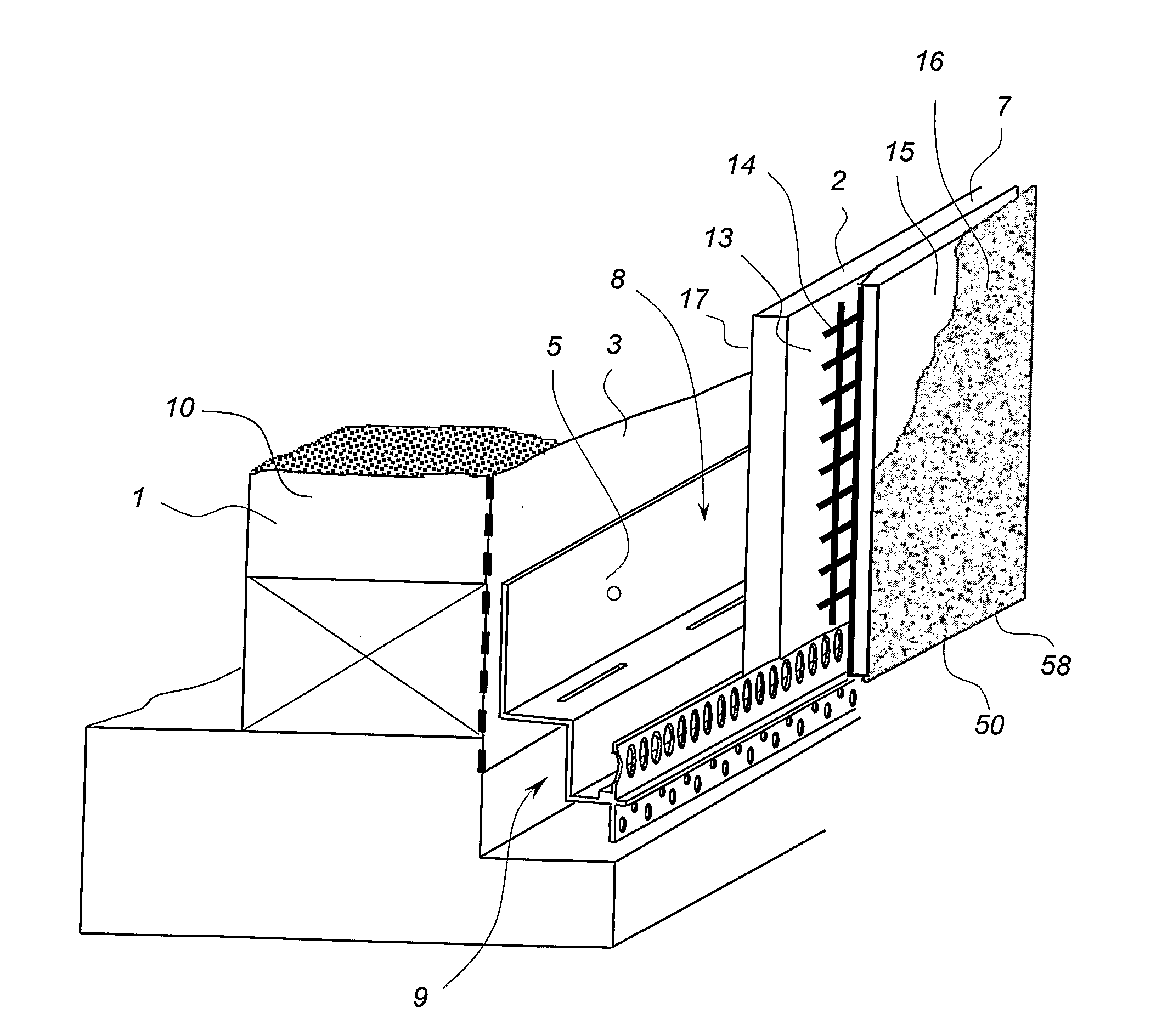
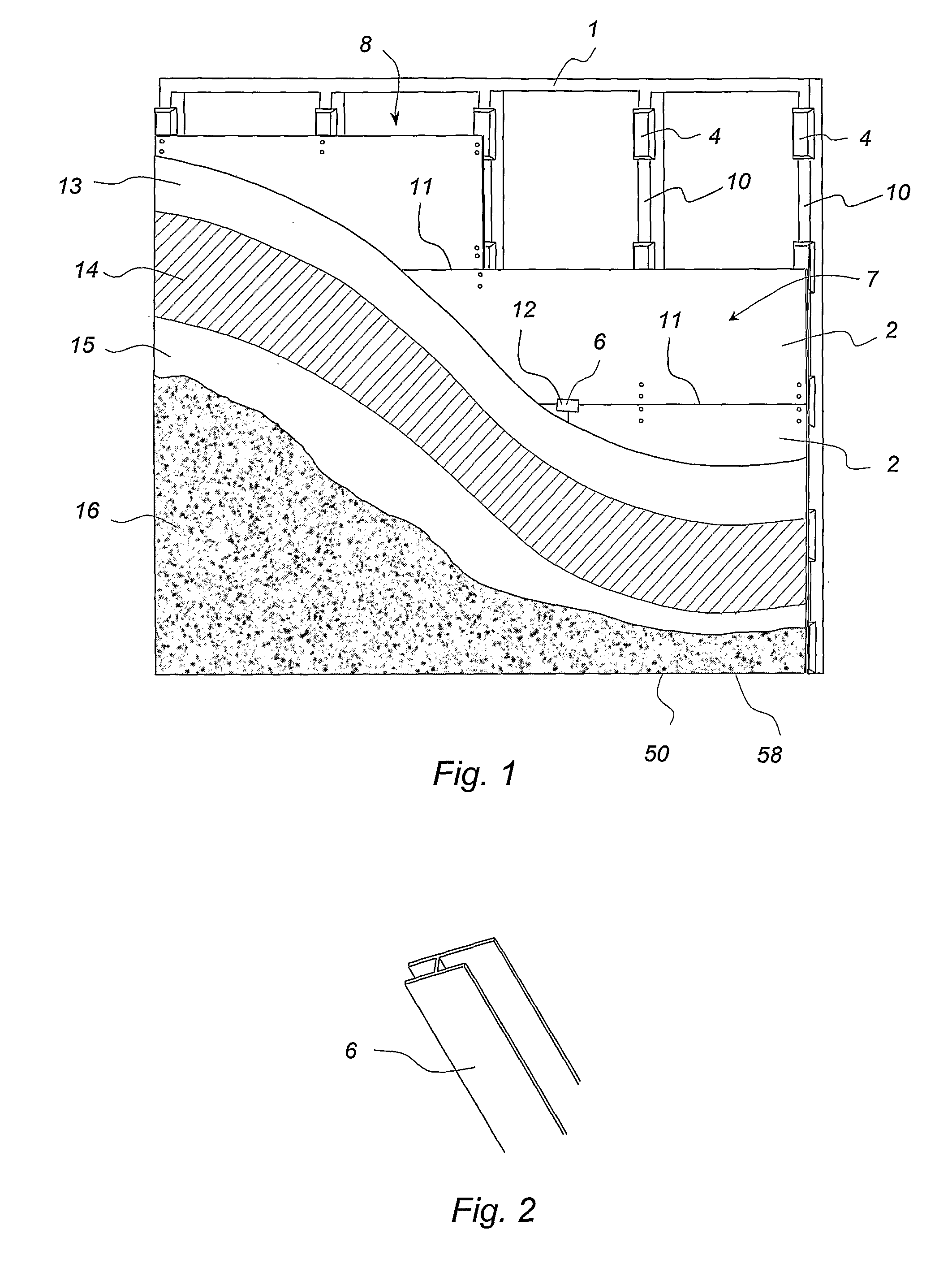
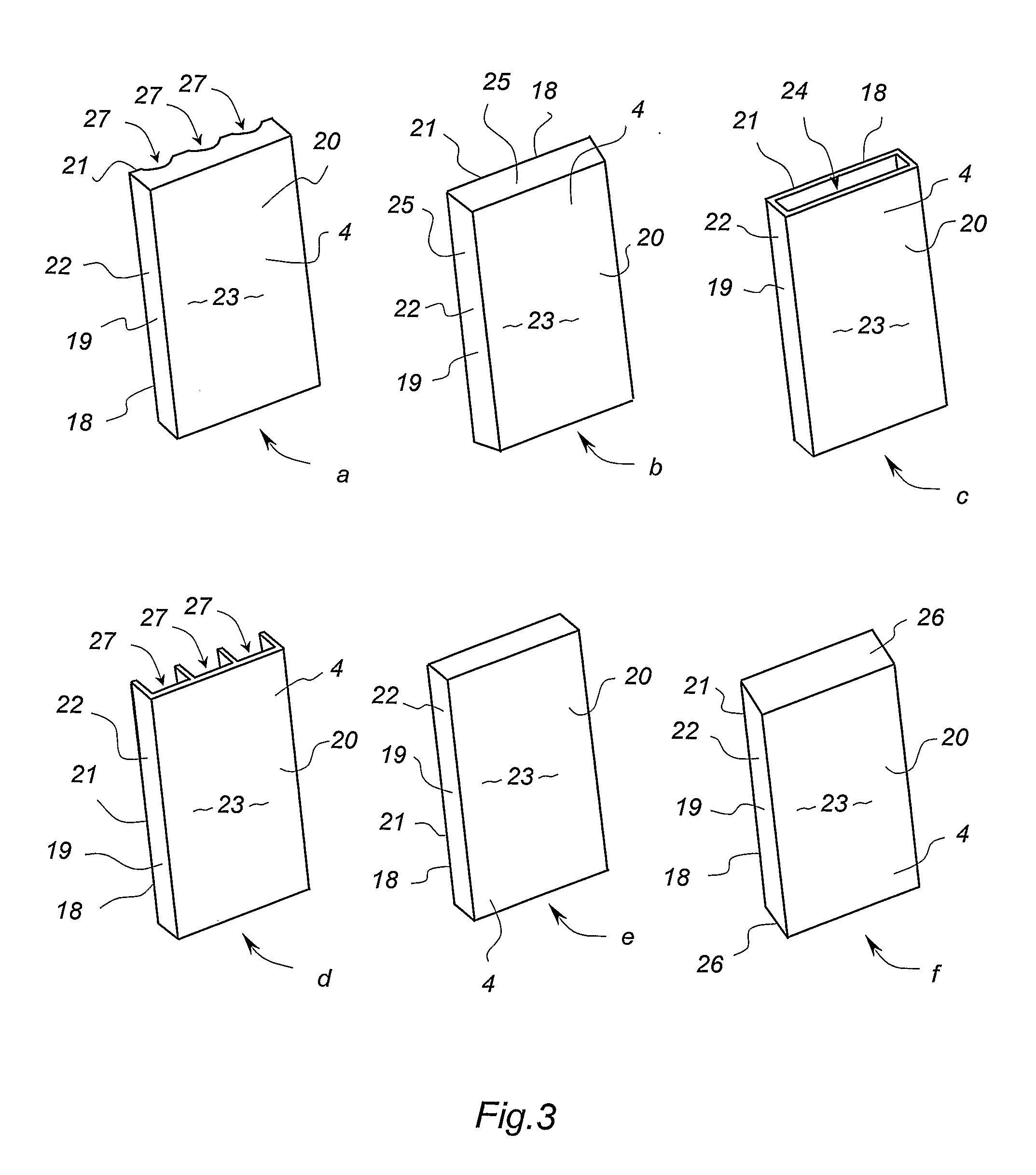
[0082]Referring to the drawings, the invention provides a cavity wall system including a wall structure 1 and a plurality of outer wall cladding panels 2. In the preferred embodiment, the wall structure is a building frame with its outer side substantially covered by moisture control means in the form of a pliable building membrane 3 defining a moisture control plane. Also preferably, the cladding panels 2 are formed substantially from fibre cement sheets, or other materials such as EPS, of sufficient strength and thickness. The system further includes a plurality of discrete mounting elements including mounting members 4, termination members or starter strips 5 and off-stud joiners 6. These are attached over the building membrane to mount the fibre cement cladding panels a predetermined distance away from the building membrane, forming a substantially flat exterior wall surface 7 and a substantially uninterrupted internal wall cavity 8 between the cladding panels and the building m...


PUM


Abstract

A cavity wall system and a method of forming a cavity wall including: a wall structure (1); a plurality of outer wall cladding panels (2); and a plurality of discrete mounting elements (4, 5, 6) for mounting the cladding panels a predetermined distance away from the wall structure (1) so as to form a substantially flat exterior wall surface (7) and a substantially uninterrupted internal wall cavity (8) between the cladding panels (2) and the wall structure (1); the mounting elements (4, 5, 6) being sized and arranged so as to allow substantially uninterrupted fluid flow throughout the cavity (8); and the system further including moisture control means defining a moisture control plane to minimise migration of liquid moisture from the cavity (8) into the wall structure (1). The invention also provides a mounting member (4) and a termination member (5) for use as mounting elements in the cavity wall system and method.

Description

FIELD OF THE INVENTION[0001]The present invention relates to a building system and method of construction of the type providing a wall cavity and a monolithic surface finish.[0002]The invention has been developed primarily for use in the construction of domestic dwellings. However, it will be appreciated the that the invention is not limited to this particular field of use, being readily adaptable to commercial, industrial and other forms of building construction.BACKGROUND TO THE INVENTION[0003]The following discussion of the prior art is intended to place the invention in an appropriate technical context and enable the advantages of it to be fully understood. However, these references should not be construed as an admission that any such art is well known or forms part of common general knowledge in the field.[0004]Modern residential housing construction is typically in the form of full masonry, timber framing with attached cladding, or a combination of masonry and timber framing ...

Claims


Application Information

Patent Timeline
IPC IPC(8): E04B2/30
CPCE04B1/74E04B1/762E04B1/765E04B2/707E04F2013/063E04F13/08E04F19/02E04F2013/065E04F13/007
Inventor GLEESON, JAMESJENSEN, JESPER G.ZARB, JOSEPH EMMANUEL
Owner JAMES HARDIE TECH LTD
Why Eureka
Try Eureka