
Method and device for disposing of air compression system effluent

a technology of air compression system and effluent, which is applied in the direction of positive displacement liquid engines, machine/engines, separation processes, etc., can solve the problems of exhaust system corrosion, condensation of moisture in compressed air stream, condensation that must be removed from the system, etc., and achieves the effect of enhancing the effectiveness of effluent vaporization and minimal corrosion potential

Inactive Publication Date: 2008-05-08
SULLAIR CORP
View PDF28 Cites 9 Cited by
  • Summary
  • Abstract
  • Description
  • Claims
  • Application Information

AI Technical Summary

Benefits of technology

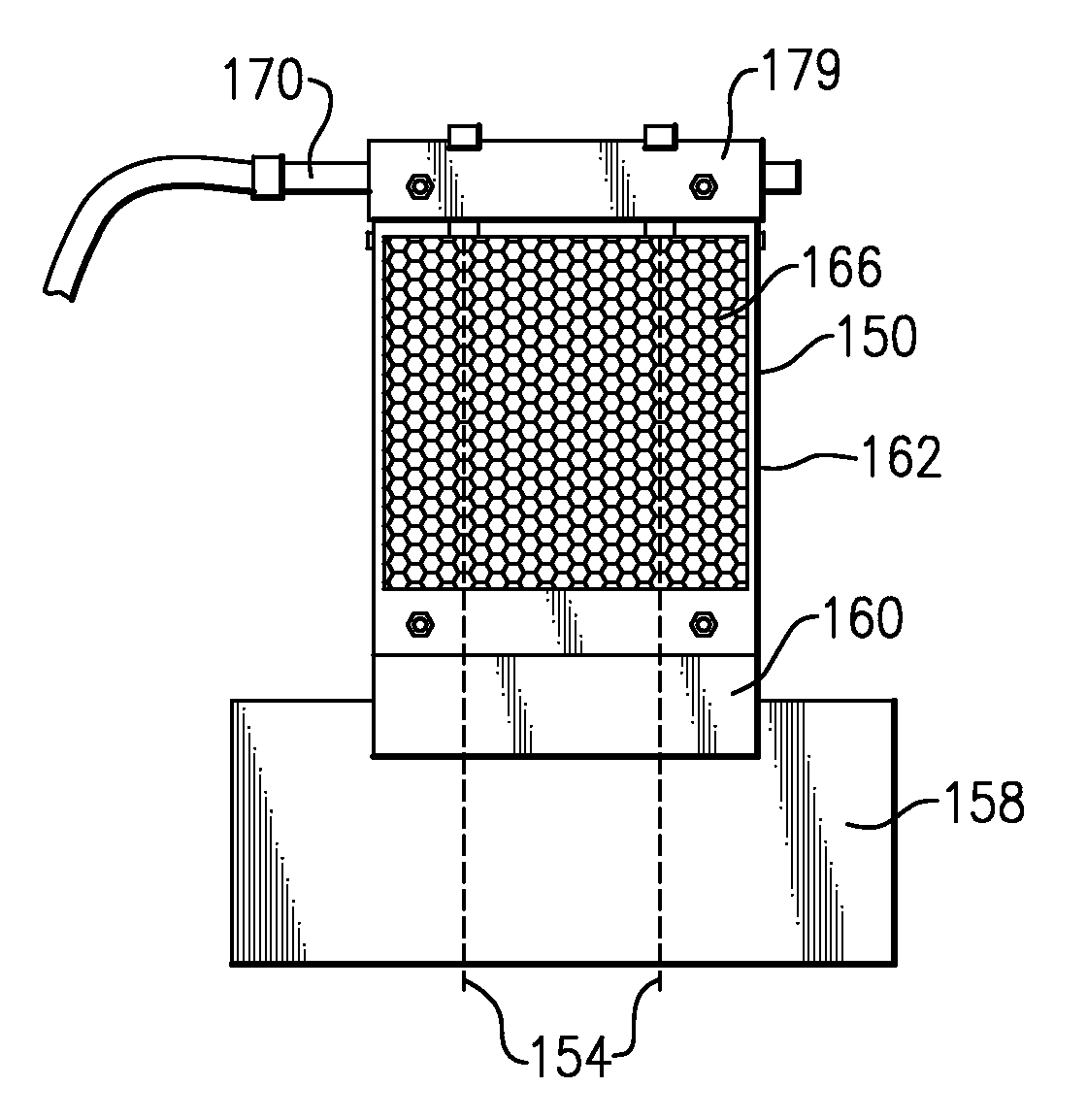
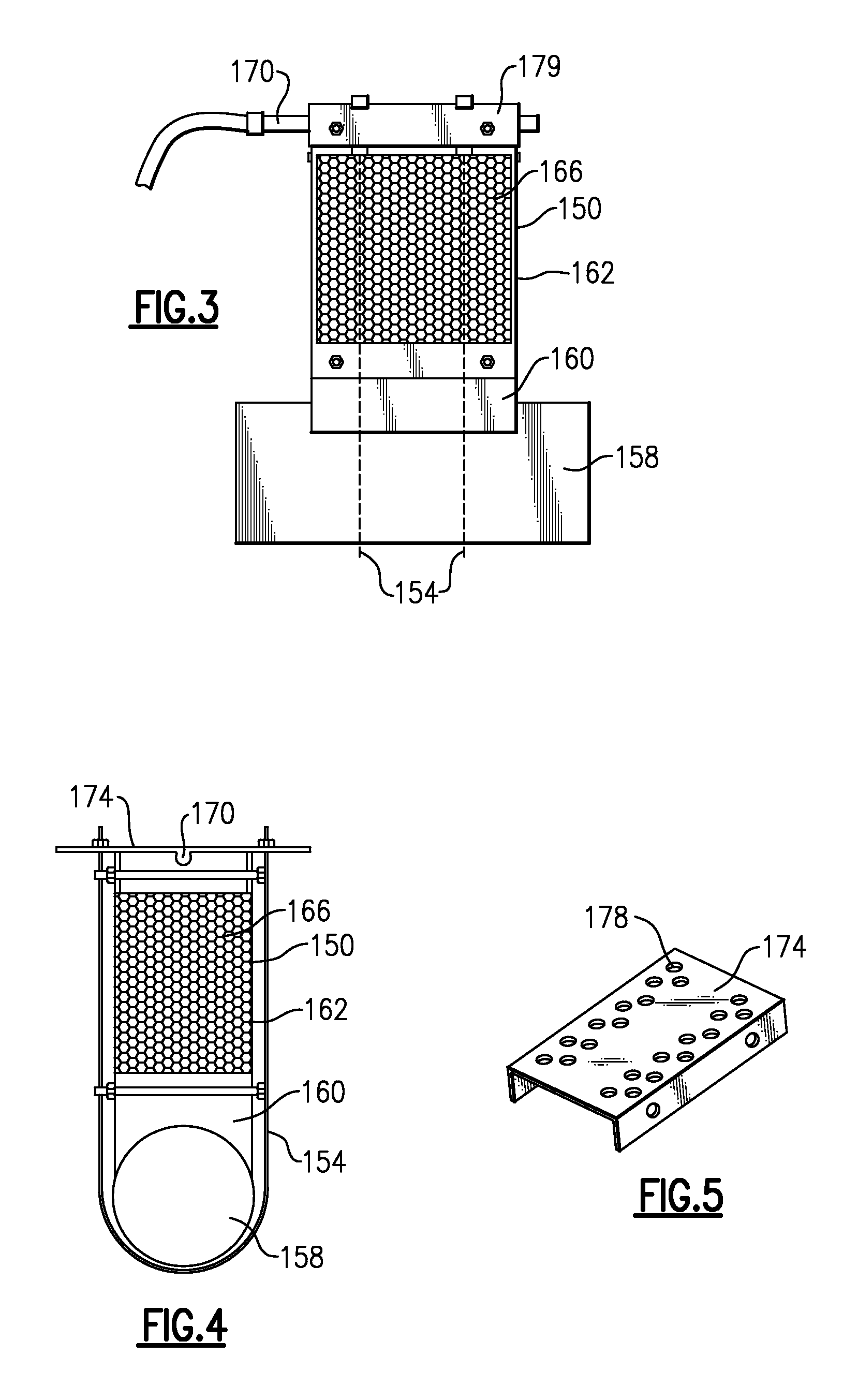
[0008]The heat exchanger, in this example a metal foam heat exchanger, secures directly to the engine. A spray tube introduces effluent from the compressed air to the thermal energy in the heat exchanger. In so doing, thermal energy from the engine exhaust pipe communicates to the effluent in the spray tube via the metal foam heat exchanger, whereupon the effluent in the spray tube vaporizes and / or combusts. A vent enables the resultant gas to escape into the atmosphere.
[0009]Accordingly, the present invention disposes of the effluent with minimal potential for corrosion and enhances the effectiveness of effluent vaporization.

Problems solved by technology

Cooling the air after the compression process is often desirable but results in condensation that must be removed from the system.
Expansion lowers the temperature of the compressed air and, if lowered below the dew point of the compressed air stream, results in condensation of moisture in the compressed air stream.
Such an approach exposes the exhaust system to the effluent, which may result in corrosion of the exhaust system.
Some exhaust systems incorporate corrosion resistant materials, however this approach substantially increases the overall cost of the exhaust system.
Further, because the exhaust system is not isolated from the engine, condensate may drain into other portions of the engine and eventually corrode them.
Lastly, the exhaust system may not reach an adequate temperature for entirely vaporizing the effluent if injected too far downstream of the exhaust manifold.
As a result, effluent may remain inside the exhaust system, which may later drain out and contaminate the environment.

Method used


Image

  • Method and device for disposing of air compression system effluent
  • Method and device for disposing of air compression system effluent
  • Method and device for disposing of air compression system effluent

Examples


Embodiment Construction

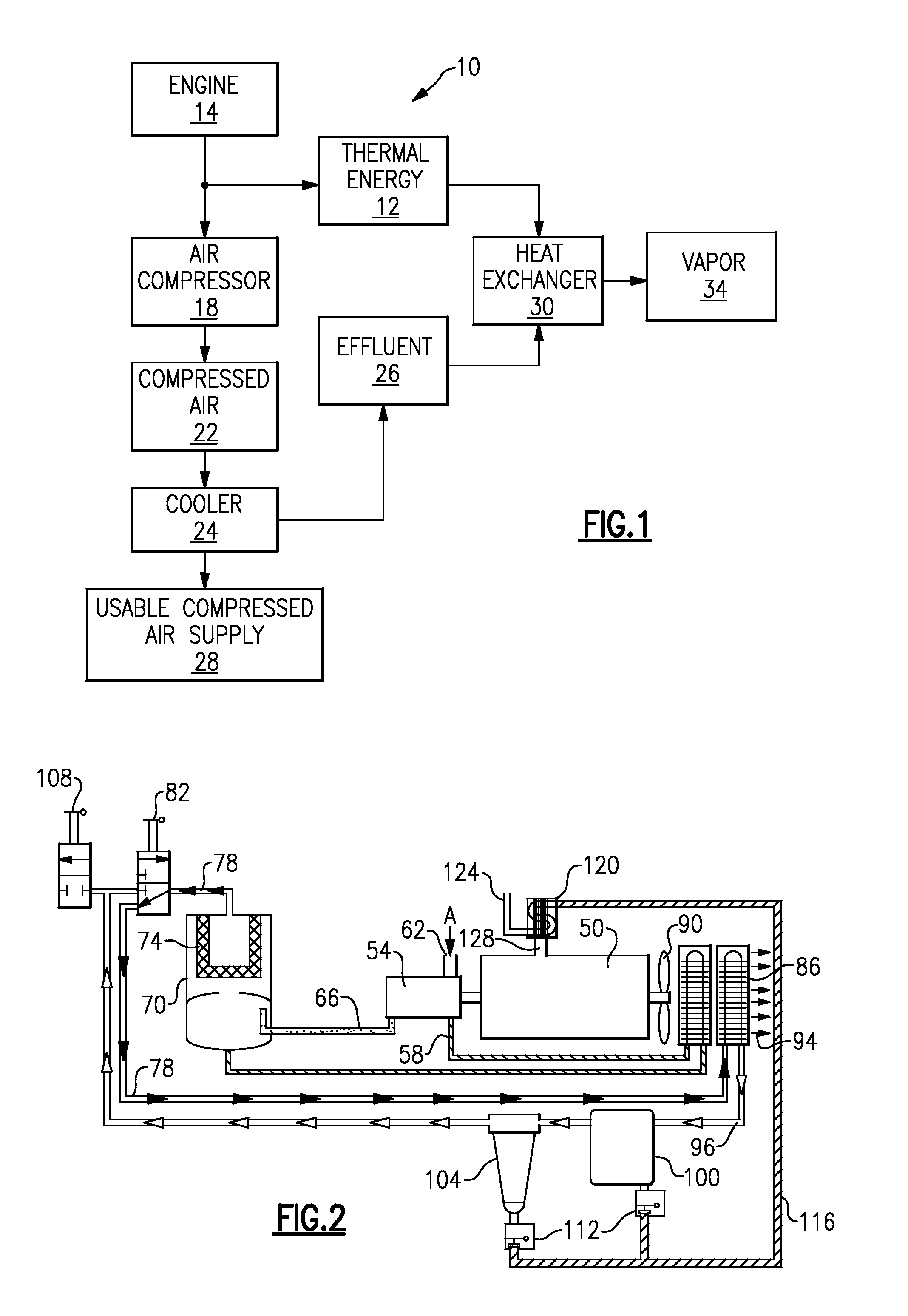
[0016]As shown in the schematic of FIG. 1, a method of effluent disposal 10 utilizes thermal energy 12 generated by an engine 14. The engine 14 drives an air compressor 18, which produces compressed air 22. A cooler 24 removes an effluent 26 byproduct from the compressed air 22 and provides a usable compressed air supply 28. Both the thermal energy 12 from the engine 14 and the effluent 26 from the cooler 18 are in communication with a heat exchanger 30.

[0017]Communicating thermal energy 12 to the heat exchanger 30 raises the temperature of the heat exchanger 30. After reaching an appropriate temperature, the heat exchanger 30 vaporizes portions of the effluent 26 upon contact. Once vaporized, the heat exchanger 30 releases vapor 34 into the atmosphere. In addition to vaporizing portions of the effluent 26, heating the effluent 26 may combust portions of the effluent 26, such as oil portions. Thus, the heat exchanger 30 vaporizes and / or combusts the effluent 26, depending on the spe...


PUM


Abstract

The method of effluent disposal thermal energy from an engine to vaporize the effluent. The engine drives an air compressor, which produces compressed air and an effluent byproduct. Both the thermal energy from the engine and the effluent from the air compressor communicate with a heat exchanger. After reaching an appropriate temperature, the heat exchanger transfer thermal energy to the effluent thereby vaporizing at least a portion of the effluent.

Description

BACKGROUND OF THE INVENTION[0001]The application relates to air compression systems, and more particularly to disposing of air compression system effluent.[0002]A typical air compression system includes an engine and a rotor assembly. The engine drives the rotor assembly to produce compressed air. Various industries rely on these types of air compression systems to generate supplies of compressed air for an array of applications, such as driving air tools, sand-blasting, painting, etc. Cooling the air after the compression process is often desirable but results in condensation that must be removed from the system. Additionally, upon delivery, expanding the compressed air produces the force necessary for the particular industrial application. Expansion lowers the temperature of the compressed air and, if lowered below the dew point of the compressed air stream, results in condensation of moisture in the compressed air stream. Air tools and other industrial applications generally requ...

Claims


Application Information

Patent Timeline
IPC IPC(8): B01D53/00
CPCF04B39/16
Inventor LAUSON, ROBERT G.DOWNING, ROBERT SCOTT
Owner SULLAIR CORP
Learn More