Combined thermal protection and surface temperature control system

a temperature control system and thermal protection technology, applied in the direction of machines/engines, lighting and heating apparatus, laminated elements, etc., can solve the problems of thermal control problems, high coolant flow rate, and the inability to protect the underlying airframe structure from destruction

Active Publication Date: 2008-05-08
THE BOEING CO
View PDF3 Cites 40 Cited by
  • Summary
  • Abstract
  • Description
  • Claims
  • Application Information

AI Technical Summary

Benefits of technology

[0006]In one aspect of the invention, a combined thermal protection and surface temperature control apparatus comprises a porous member comprising an entrance side, and a separate exit side. One or more coolant entrance channels extend through the entrance s

Problems solved by technology

There are a number of thermal control problems which may arise in high heat flux environments, such as those encountered in air breathing engines, during hypersonic flight of aircraft, or in other non-aeronautical applications.
The first problem concerns protecting the underlying airframe structure from destruction by the high heat flux via a thermal protection system (TPS).
The other problem concerns controlling the temperature of a surface bounding a high velocity flow to a particular level, while that surface is simultaneously being subjected to high heat flux.
Back side cooling, film cooling, and transpiration cooling methods may all potentially deal with both problems in a single design, but may have significant drawbacks.
For instance, they may require high coolant flow rates and may depend on the delivery of coolant to be cooled through a heavy

Method used


Image

  • Combined thermal protection and surface temperature control system
  • Combined thermal protection and surface temperature control system
  • Combined thermal protection and surface temperature control system

Examples


Embodiment Construction

[0016]The following detailed description is of the best currently contemplated modes of carrying out the invention. The description is not to be taken in a limiting sense, but is made merely for the purpose of illustrating the general principles of the invention, since the scope of the invention is best defined by the appended claims.

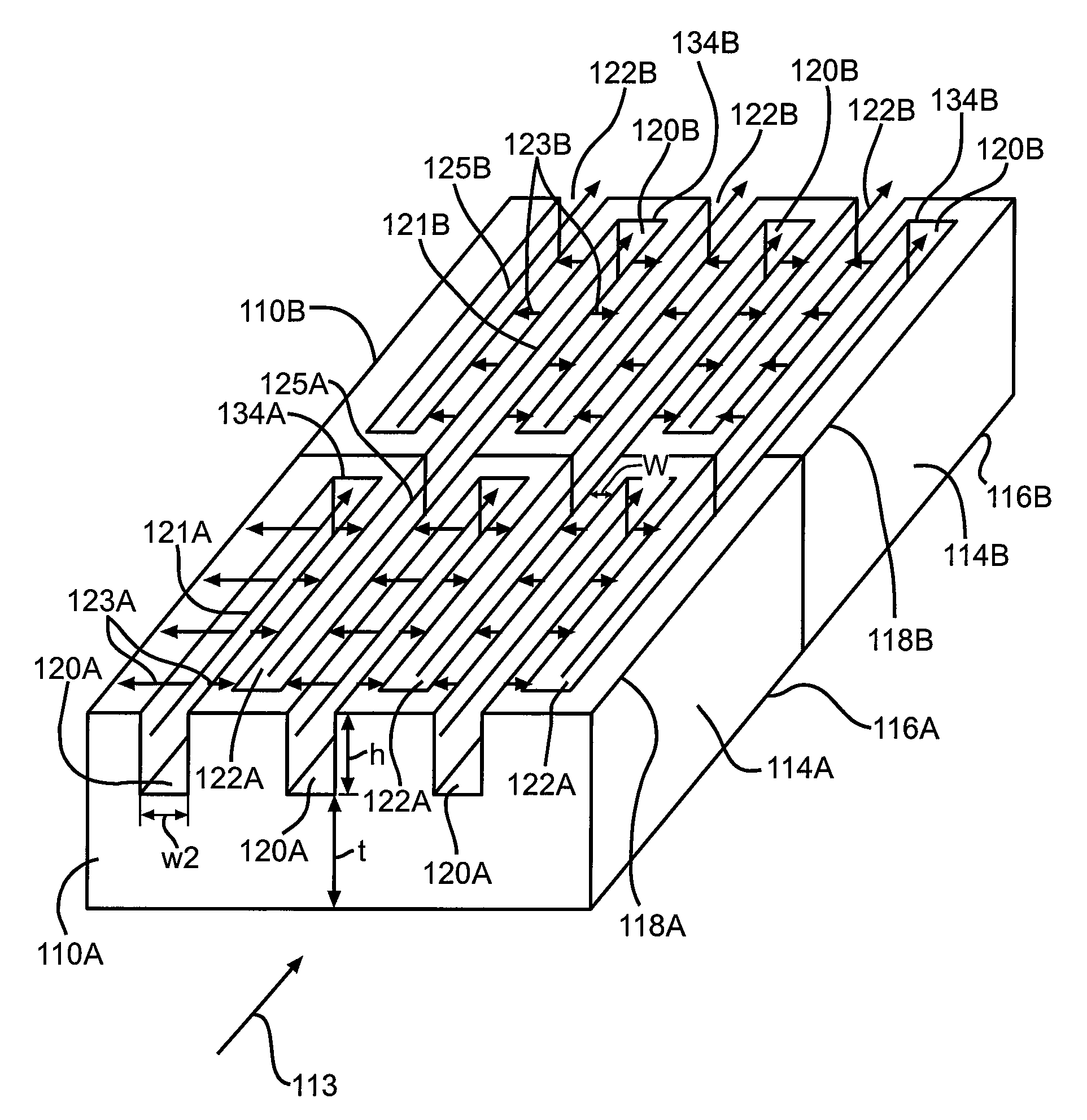
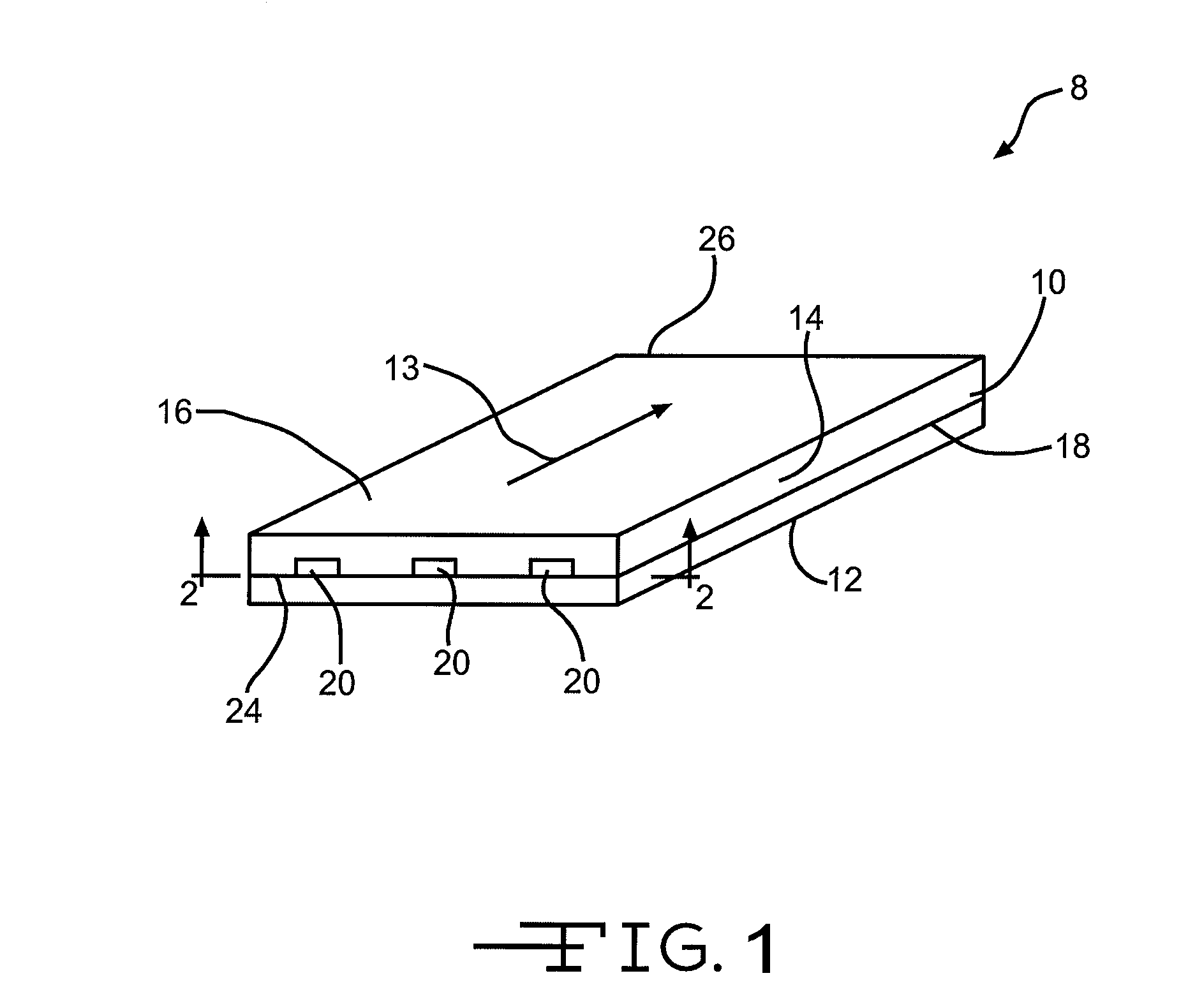
[0017]In one embodiment of the invention, as depicted in FIG. 1, a thermally protected, surface temperature controlled apparatus 8 is provided. The thermally protected and surface temperature controlled apparatus 8 may comprise a thermal protection apparatus 10 which has an attachment side 18 which is attached, utilizing a RTV silicone adhesive, to a member 12 to which it is providing thermal protection from an environment hot flow 13. In other embodiments, the thermal protection apparatus 10 may be attached to the thermally protected member 12 utilizing any type of attachment mechanism. The thermally protected member 12 may comprise any type of surface...


PUM

PropertyMeasurementUnit
Sizeaaaaaaaaaa
Densityaaaaaaaaaa
Porosityaaaaaaaaaa

Abstract

The invention relates to a combined thermal protection and surface temperature control apparatus. In one embodiment, a combined thermal protection and surface temperature control apparatus comprises a porous member having an entrance side, and a separate exit side. One or more coolant entrance channels extend through the entrance side, extend part-way through the porous member, and end within the porous member before reaching the exit side. Conversely, one or more coolant exit channels begin within the porous member, extend through a portion of the porous member, and extend through the exit side. The coolant entrance and exit channels may be parallel and may alternate. The channels may only extend across a portion of the thickness of the porous member.

Description

BACKGROUND OF THE INVENTION[0001]There are a number of thermal control problems which may arise in high heat flux environments, such as those encountered in air breathing engines, during hypersonic flight of aircraft, or in other non-aeronautical applications. The first problem concerns protecting the underlying airframe structure from destruction by the high heat flux via a thermal protection system (TPS). The other problem concerns controlling the temperature of a surface bounding a high velocity flow to a particular level, while that surface is simultaneously being subjected to high heat flux.[0002]Back side cooling, film cooling, and transpiration cooling methods may all potentially deal with both problems in a single design, but may have significant drawbacks. For instance, they may require high coolant flow rates and may depend on the delivery of coolant to be cooled through a heavy, expensive, structural ducting and plenum system. A plenum may have to be provided directly beh...

Claims


Application Information

Patent Timeline
IPC IPC(8): F28F3/12F01P11/00B60R27/00B64G1/46B64C7/00B60R99/00
CPCB64C1/40Y10T29/4935Y02T50/46F28F13/003F28F3/12F28F7/02Y02T50/40
Inventor BEHRENS, WILLIAM W.TUCKER, ANDREW R.
Owner THE BOEING CO
Why Eureka
Try Eureka