

Systems, articles, and methods for removing water from hydrocarbon fluids
a technology of hydrocarbon fluid and system, applied in the direction of filtration separation, membranes, separation processes, etc., can solve the problems of fuel filter plugging, affecting the performance and operation of engines, and emulsified water contamination in fuel
- Summary
- Abstract
- Description
- Claims
- Application Information
AI Technical Summary
Benefits of technology
Problems solved by technology
Method used
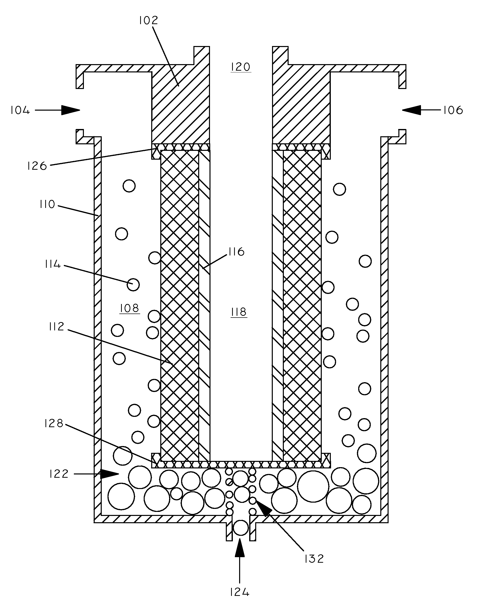
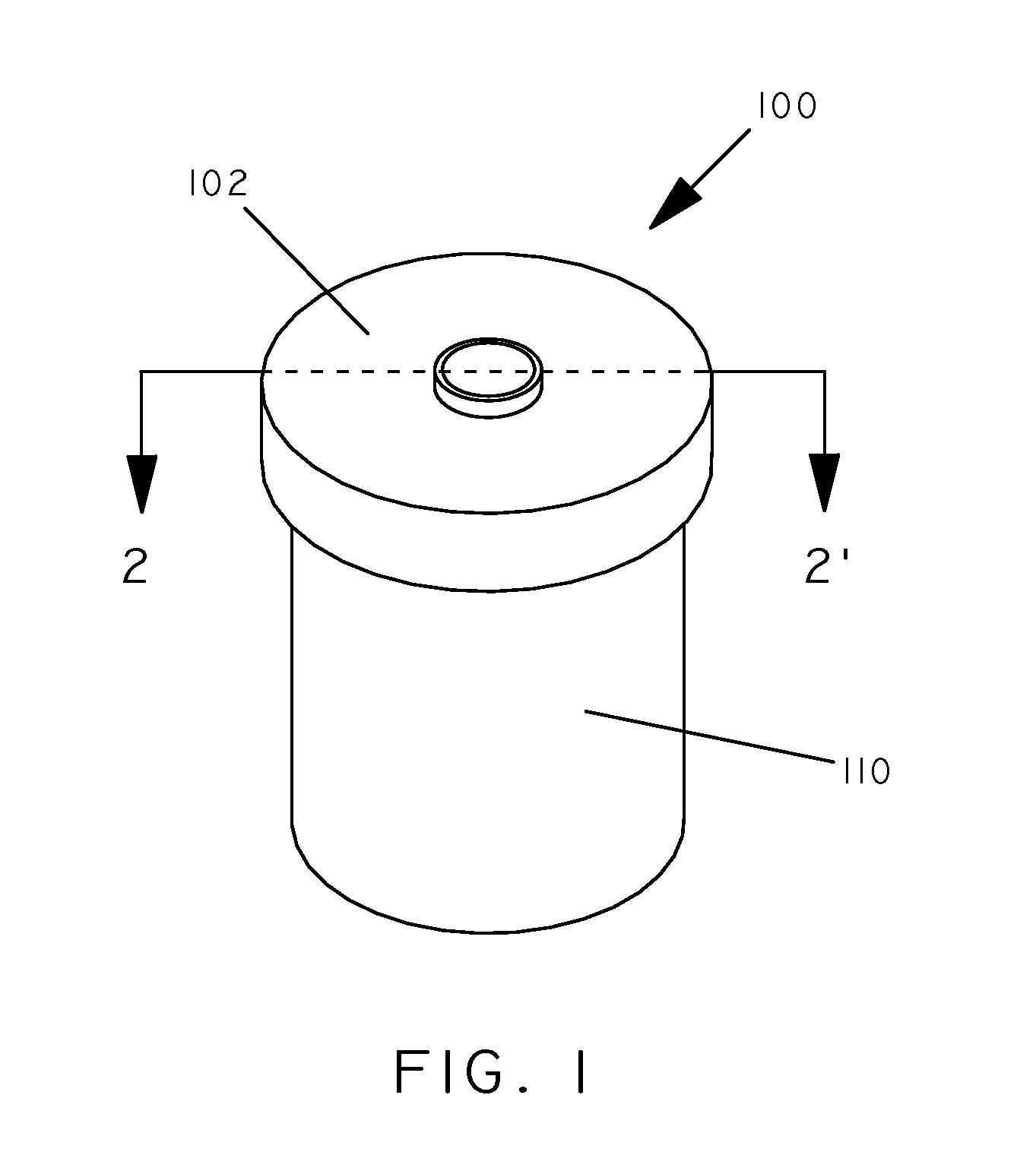
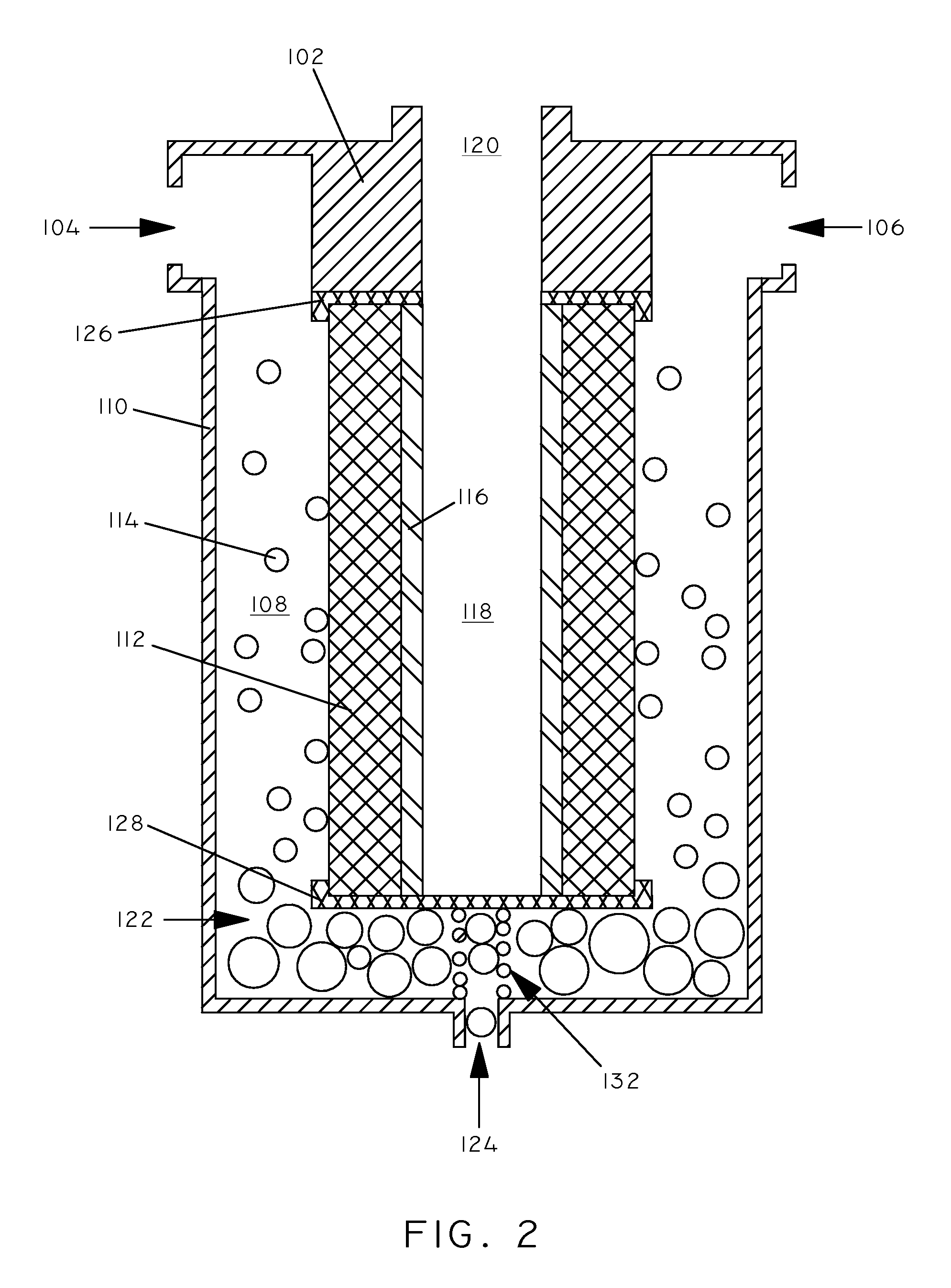
Image

Examples
example 1
Preparation of Separation Article #1
[0042]A layer of expanded PTFE was thermally welded to a substrate of polyester (0.75 ounces per square yard) (REEMAY 2275 available from BBA FIBERWEB Filtration) to form separation article #1. The PTFE layer had an average pore size of 0.2 μm as measured according to ASTM E1294 using a porosimeter (Porous Materials, Inc., Ithaca, N.Y.). The permeability (Frazier permeability) of the PTFE was 0.65 cfm / ft2 as measured according to ASTM D737. The PTFE layer had a thickness of 3 mils. The permeability (Frazier permeability) of the substrate was 925 cfm / ft2 as measured according to ASTM D737. The substrate had a thickness of 6 mils.
example 2
Preparation of Separation Article #2
[0043]A layer of expanded PTFE was thermally welded to a substrate of polypropylene felt (12.5 ounces per square yard) (Southern Felts, Augusta, S.C.) to form separation article #2. The PTFE layer had an average pore size of 0.7 μm as measured according to ASTM E1294 using a porosimeter (Porous Materials, Inc., Ithaca, N.Y.). The permeability (Frazier permeability) of the PTFE was 1.5 cfm / ft2 as measured according to ASTM D737. The PTFE layer had a thickness of 3 mils. The permeability (Frazier permeability) of the substrate was 40 cfm / ft2 as measured according to ASTM D737. The substrate had a thickness of 8.5 mils.
example 3
Preparation of Separation Article #3
[0044]A layer of asymmetric PTFE was thermally welded to a bicomponent substrate of polypropylene and polyethylene to form separation article #3. The PTFE layer had with a pore gradient from 0.8 to 0.1 μm along the membrane thickness as measured according to ASTM E1294 using a porosimeter (Porous Materials, Inc., Ithaca, N.Y.). The permeability (Frazier permeability) of the PTFE was 0.4 cfm / ft2 as measured according to ASTM D737. The PTFE layer had a thickness of 1.0 mils. The permeability (Frazier permeability) of the substrate was 67 cfm / ft2 as measured according to ASTM D737. The substrate had a thickness of 6 mils.
PUM
| Property | Measurement | Unit |
|---|---|---|
| Length | aaaaa | aaaaa |
| Length | aaaaa | aaaaa |
| Fraction | aaaaa | aaaaa |
Abstract
Description
Claims
Application Information