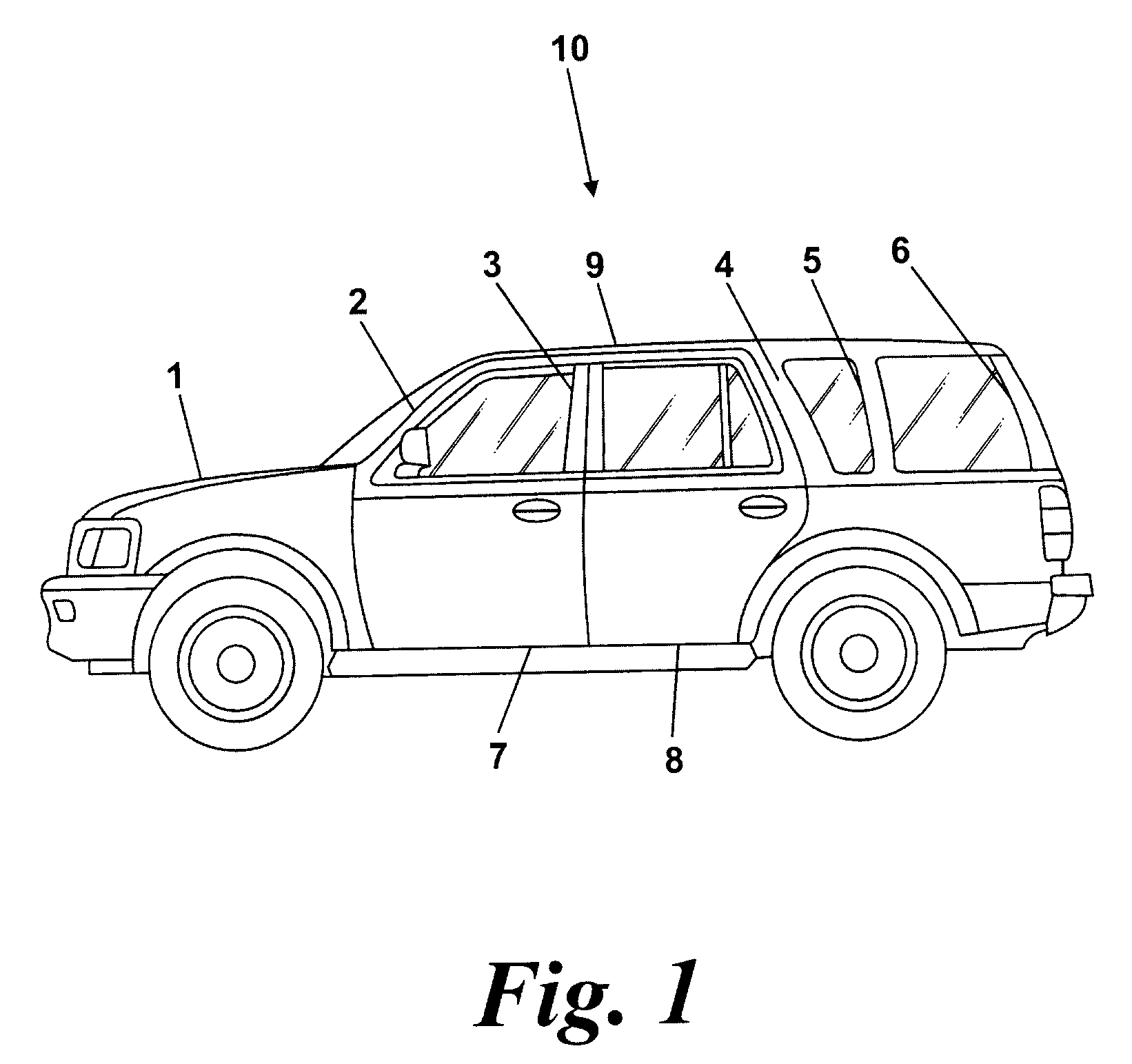
[0026]With reference to FIG. 1 there is shown a motor vehicle 10 having a body structure 1 comprised of a number of aluminum panels fastened to a number of underlying aluminum structural members (not visible on FIG. 1) and aluminum side structural members including an “A” post 2, a “B” post 3, a “C” post 4, a “D” post 5 and a “E” post 6, the side structural members being used to connect a roof 9 to a lower body structure. The vehicle 10 also includes a number of doors including a front door 7 and a rear door 8.
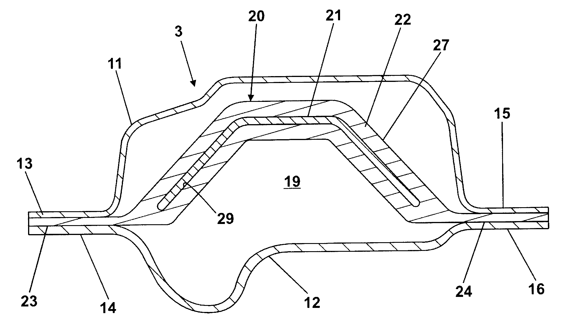
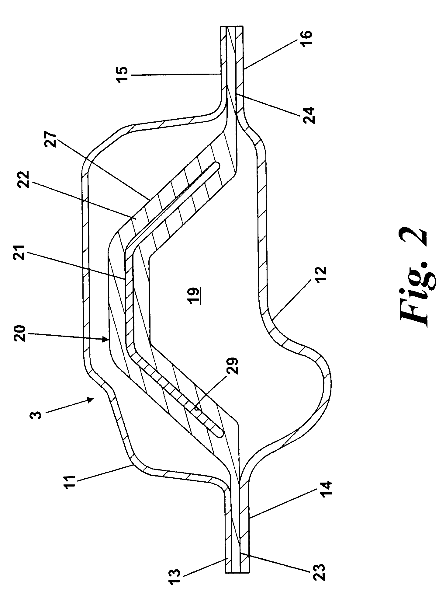
[0027]Referring further to FIG. 2, the “B” post 3 is formed from a first elongate panel member in the form of an aluminum pressing or stamping 11 and a second elongate panel member in the form of another aluminum pressing or stamping 12. The first pressing 11 has a first flange 13 extending along one edge and a second flange 15 extending along an opposite edge. Similarly the second pressing 12 has a first flange 14 extending along one edge and a second flange 16 extending along an opposite edge. The first and second pressings 11 and 12 when assembled together form an internal volume 19 in which is fastened a reinforcing member 20.
[0028]The reinforcing member 20 comprises a steel core 21 encased in an aluminum casing 22. The core 21 is formed of profiled flat strip, being non-planar in its transverse cross-section so as to improve its resistance to bending. The casing 22 has a body portion 27 in which the core 21 is located and two longitudinally extending flanges 23, 24 of uniform width which extend along the length of the body portion 27.
[0029]The reinforcing member 20 can be manufactured in the following manner. The steel core 21 is formed into a constant section profile having the desired shape, e.g. by rolling from flat strip. The aluminum casing 22 is then extruded to form a constant section profile with an internal wall defining a closed section cavity 29. The shape of the cavity 29 within the casing 22 is designed to match the geometry of the steel core 21 and is sized so that the steel core 21 can be loosely fitted into the cavity 29. The casing 22 is then co-drawn with the steel core 21 through a die to bind the casing 22 to the core 21 in a manner substantially as described in JP57-001516A, hereby incorporated by reference. The residual pressure of the casing 22 on the core 21 may well be sufficient to bind the casing 22 to the core 21 but for additional bonding an adhesive may be introduced between the core and the casing. If adhesive is applied, it can be applied either to only the core 21, to only the internal wall defining the cavity 29 in the casing 22, or to both surfaces. If adhesive is used, then this can be cured and the casing 22 can be heat treated at the same time. After drawing, an elongate member or beam is produced which can be left straight and cut to length to form the reinforcing member 20. Alternatively, the elongate member or beam can be cut to length and then be bent prior to heat treatment to form an appropriately shaped reinforcing member.
[0030]The reinforcing member 20 is fastened to the two pressings 11, 12 by placing the reinforcing member 20 onto the first pressing 11 with its flanges 23, 24 resting on and aligned with the first and second flanges 13, 15 of the first pressing 11. The first and second flanges 13, 15 of the first pressings 11 and the flanges 23, 24 of the reinforcing member 20 are then tacked together (i.e. joined at well-spaced locations) using self-piercing rivets, e.g. as described in U.S. Pat. No. 5,752,305. The rivets only have to pass through aluminum and so relatively low forces are required for this process. The second pressing 12 is then placed on top of the reinforcing member 20 so that its first and second flanges 14, 16 lie on top of and are aligned with the flanges 23, 24 of the reinforcing member 20. The first and second flanges 13, 15 and 14, 16, of the two pressings 11, 12 and the flanges 23, 24 of the reinforcing member 20, are then secured together using self-piercing rivets as referred to above but at closer locations.
[0031]Alternatively, the reinforcing member 20 is fastened to the two pressings 11, 12 by placing the reinforcing member 20 onto one of the first and second pressings 11 or 12 with its flanges 23, 24 resting on and aligned with the first and second flanges 13, 15 or 14, 16 of the first or second pressing. The other pressing 12 or 11 is then placed on top of the reinforcing member 20 so that its first and second flanges 14, 16 or 13, 15 lie on top of and are aligned with the flanges 23, 24 of the reinforcing member 20. The first and second flanges 13, 15 and 14, 16 of the two pressings 11, 12 and the flanges 23, 24 of the reinforcing member 20, are then secured together using self-piercing rivets as described above.
[0032]The completed structural member 3 can then be assembled into the body structure 1. Any panels or other members forming the body structure that mate with the structural member 3 are designed to match it so that flanges or designated matching joining areas can be brought into contact with the flanges of the structural member 3 and be secured to it, preferably by self-piercing rivets. However, it will be appreciated that because no steel is present in the flanges of the structural member 3, the structural member could be welded or bonded in position, e.g., as described in EP0127343.
[0033]Alternatively, the reinforcing member 20 may be fastened to existing panels of the body structure 1, the body panels that mate with the reinforcing member having flanges that correspond to the flanges of the reinforcing member to form a structural member which is integral with the body structure.
[0034]After co-drawing, the width of the flanges 23, 24 are of the maximum width required to produce the desired flange shape. Prior to assembly of the reinforcing member 20 into the two pressings 11, 12, the flanges 23, 24 can be trimmed so that their width is varied along their respective lengths so that the reinforcing member 20 conforms to the shape required of the structural member 3. This is described in FIG. 3. The flanges 23, 24 may be machined to produce the required shape or may be sheared or cut by laser. Alternatively, if required, the flanges 13, 14, 15, 16 of the pressings 11, 12 may also have the same maximum width when the pressings are assembled and riveted to the reinforcing member 20 so that all the flanges 13, 14, 15, 16&23, 24 are trimmed to the required shape in the same operation. After the trimming operation the reinforcing member 20 may be bent to fit the other components as required. In a further variation, the reinforcing member 20 may be bent first and the trimming operation performed subsequently.
[0035]In a first alternative embodiment shown in FIG. 4, parts which are the same as those shown in FIG. 2 carry the same reference while those which are similar carry the same reference with the addition of 100. The reinforcing member 120 differs from that described with reference to FIG. 2 in that the casing 122 is formed with transition portions 125, 126 that change the stress gradient between the flanges 123, 124 and the body portion 127 when a transverse bending load is applied to the structural member 3. The reinforcing member 120 is manufactured exactly as before and so will not be described again in detail.
[0036]In a second alternative embodiment shown in FIG. 5, parts which are the same as those shown in FIG. 2 carry the same reference while those which are similar carry the same reference with the addition of 200. The reinforcing member 220 differs from that described with reference to FIG. 2 in that the casing 222 is formed with transition portions 225, 226 similar to the transition portions 125, 126 in FIG. 4 to change the stress gradient between the flanges 223, 224 and the body portion 227 when a transverse bending load is applied. Additionally, in order to minimize the stress raising effect of the steel core 221 on the casing 222 when subject to a bending load, the steel core 221 has end sections 231, 232 which are bent back upon themselves to form a double-thickness. This bending back increases the effective radius at the end of the steel core 221 thereby reducing its stress raising effect on the casing 222. The reinforcing member 220 is manufactured exactly as before and so will not be described again in detail.
[0037]FIG. 6 shows another embodiment of a reinforcing member 320 which is intended to be a direct replacement for the reinforcing members 20, 120, 220 described with reference to FIGS. 2 to 5. Nevertheless, there are many parts of the structural member 3 which remain substantially the same as described in relation to FIGS. 2 to 5 so carry the same reference while those which are similar carry the same reference as in FIG. 2 with the addition of 300.
[0038]In this embodiment, the reinforcing member 320 comprises a steel core 321 of a tubular construction which is oval in transverse cross-section so as to improve its resistance to bending, the oval being elliptical. Transition portions 325, 326 change the stress gradient between the flanges 323, 324 and the body portion 327 when a transverse bending load is applied to the structural member 3. The thickness of the body portion 327 of the casing 322 surrounding the core 321 is greater than the thickness of the core 321 to avoid rupture of the casing 322 when the core 321 is deformed.
[0039]The reinforcing member 320 is manufactured as before and so will not be described again in detail. It is sufficient to say that the tubular core 321 is manufactured by extrusion or by any other convenient method such as rolling and seam welding, the core 321 is then inserted in the cavity 329 in the body portion 327 and the co-assembled parts are drawn together through a die and cut to length and bent if required to produce the reinforcing member 320. As before, adhesive can be used if required between the core 321 and the wall of the cavity 29 in the body portion 327.
[0040]In a further embodiment shown in FIG. 7, parts which are the same as those shown in FIG. 6 carry the same reference while those which are similar carry the same reference with the further addition of 100. The reinforcing member 420 differs from that described with reference to FIG. 6 in that while the core 421 is of a tubular construction that is oval in transverse cross-section, in this case the oval has parallel sides which are also parallel to the flanges 423, 424 and semi-circular end sections connected to the flanges 423, 424 through the transition portions 425, 426.
[0041]In another embodiment shown in FIG. 8, parts which are the same as those shown in FIG. 6 carry the same reference while those which are similar carry the same reference with the further addition of 200. The reinforcing member 520 differs from that described with reference to FIG. 6 in that the core 521, while also being of a tubular construction, is trapezoidal in transverse cross-section, again to improve its resistance to bending. This trapezoidal section is useful where the section of the structural member 3 would not allow a symmetrical section of reinforcing member such as the reinforcing members 320, 420 shown in FIGS. 6 & 7.
[0042]The alternative form of “B” post 703 shown in FIG. 9 has a number of similarities with the one shown in FIG. 2 so where appropriate the same references are used but with the addition of 700. The “B” post 703 differs from those previously described in that it uses only one pressing 712 in combination with a reinforcing member 720. The reinforcing member 720 comprises a steel core 721 encased in an aluminum casing 722, the core 721 being non-planar in transverse cross-section to improve its resistance to bending. The casing 722 has a body portion 727 in which is located the core 721 and two longitudinally extending flanges 723, 724 which are of uniform width and extend along the length of the body portion 727. The reinforcing member 720 is manufactured exactly as before and so will not be described again in detail.
[0043]The reinforcing member 720 is fastened to the pressing 712 by placing the reinforcing member 720 onto the second pressing 712 such that its flanges 723, 724 rest upon and are aligned with the flanges 714, 716 of the pressing 712. The flanges 714, 716 of the pressing 712 and the flanges 723, 724 of the reinforcing member 720 are then secured together using self-piercing rivets to form the structural member 703. This arrangement has the advantage of the use of less components and potentially lower weight but can only be used when the reinforcing member 720 can be produced in a shape required to form part of the outer surface of the structural member 703. This might be where the exposed surface of the reinforcing member 720 is hidden by internal trim components of the vehicle.
[0044]It will be appreciated that the invention is generally beneficial when the core is of a material that has a yield strength sufficiently high to prevent it being secured using self-piercing rivets but that a core of ultra high yield strength steel will provide the greatest strength. In one proposed use of the invention it was calculated that an aluminum casting or extrusion of approximately 10 to 12 mm wall thickness with thin rivetable joining flanges could be replaced by a structural member according to the invention having a steel core 1.5 mm thick. It was estimated that a 950 MPa yield heat-treated boron steel for the core would provide four times the yield strength of the known aluminum solution and provide a component approximately 80% of the weight of the solely aluminum design and 50% of an all steel design. One example of an ultra high strength steel suitable for use for the core has a composition by mass of Carbon (C) 0.20%-0.25%, Silicon (Si) 0.15%-0.50%, Manganese (Mn) 1.00%-1.40%, Phosphorus (P)<0.030%, Sulfur (S)<0.025%, Chromium (Cr) 0.10%-0.35%, Molybdenum (Mo)<0.35%, Boron (B) 0.0015%-0.0050%. Additionally minute amounts of Aluminum (Al) and Titanium (Ti) may have been added for manufacturing purposes.
[0045]Although the invention has been described above as including a reinforcing member having a steel core and an aluminum casing it will be appreciated that other combinations could be produced with advantageous effect. For example, a high yield strength steel core could be used to reinforce a casing made from another non-ferrous lightweight material such as a magnesium alloy or a casing made from a low yield strength steel capable of being secured using self-piercing rivets. Similarly, although the invention has been described with reference to a “B” post, it will be appreciated that it could be used for other structural members on a motor vehicle including movable components such as a suspension arm. Also, although the reinforcing member has been described as joined to pressings to form the structural member, it may be joined to panel members made by other means such as extrusion or casting.