Apparatus and method for detecting rotation angle of rotating body

a technology of rotating bodies and apparatuses, which is applied in the direction of motors/generators/converter stoppers, instruments, dynamo-electric converter control, etc., can solve the problems of increasing the production cost of rotation angle detection apparatuses, and achieve the effect of reducing the cpu load

Inactive Publication Date: 2008-05-08
DENSO CORP
View PDF6 Cites 7 Cited by
  • Summary
  • Abstract
  • Description
  • Claims
  • Application Information

AI Technical Summary

Benefits of technology

[0026]According to the present invention, it is possible to reduce the CPU load at the time of detecting a rotation angle of a rotating body on the basis of a resolver signal outputted from a resolver mounted on the rotating body.

Problems solved by technology

However, this conventional technique has a problem in that since the peak value of the resolver signal is estimated through computation on a plurality of AD-conversion results, the CPU load becomes large, and accordingly a high performance CPU is needed, which increases the production cost of the rotation angle detection apparatus.

Method used


Image

  • Apparatus and method for detecting rotation angle of rotating body
  • Apparatus and method for detecting rotation angle of rotating body
  • Apparatus and method for detecting rotation angle of rotating body

Examples


Embodiment Construction

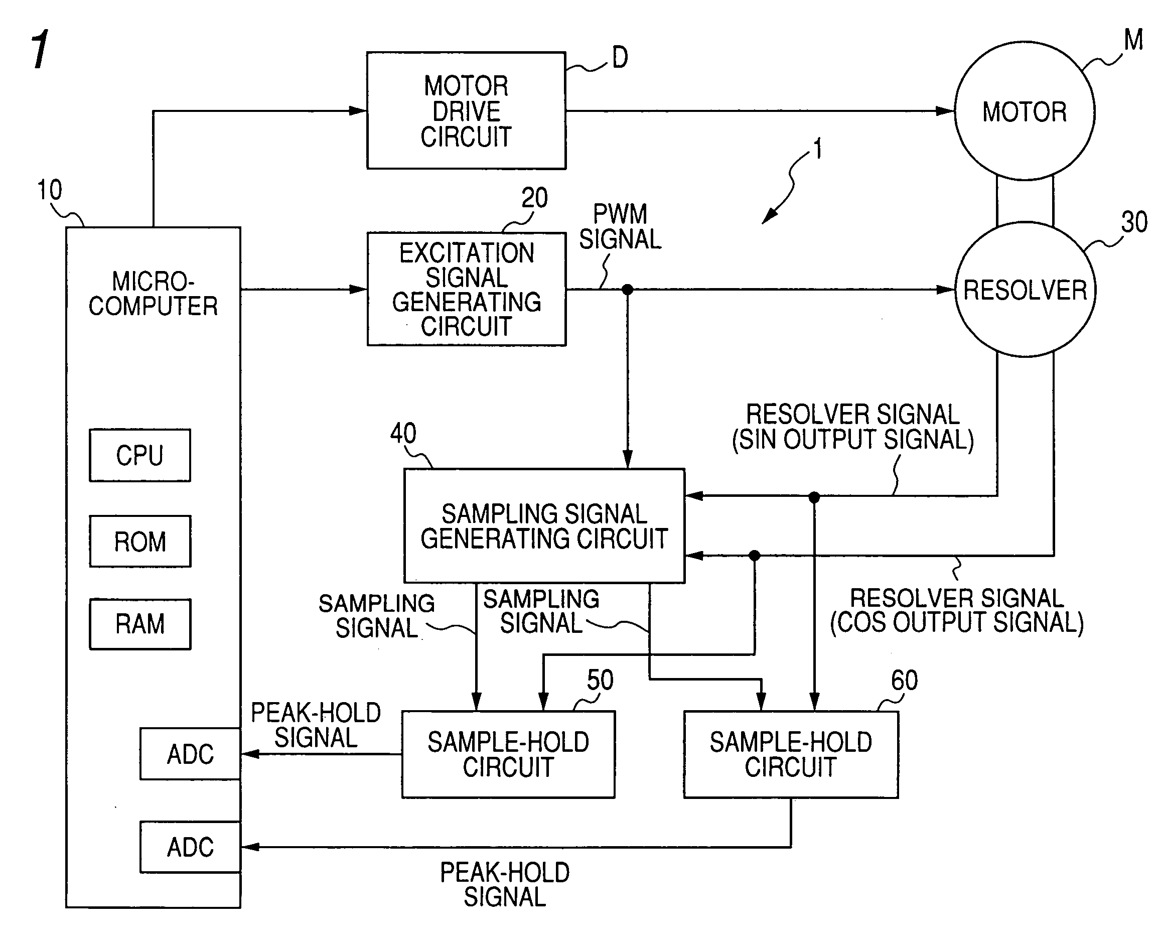
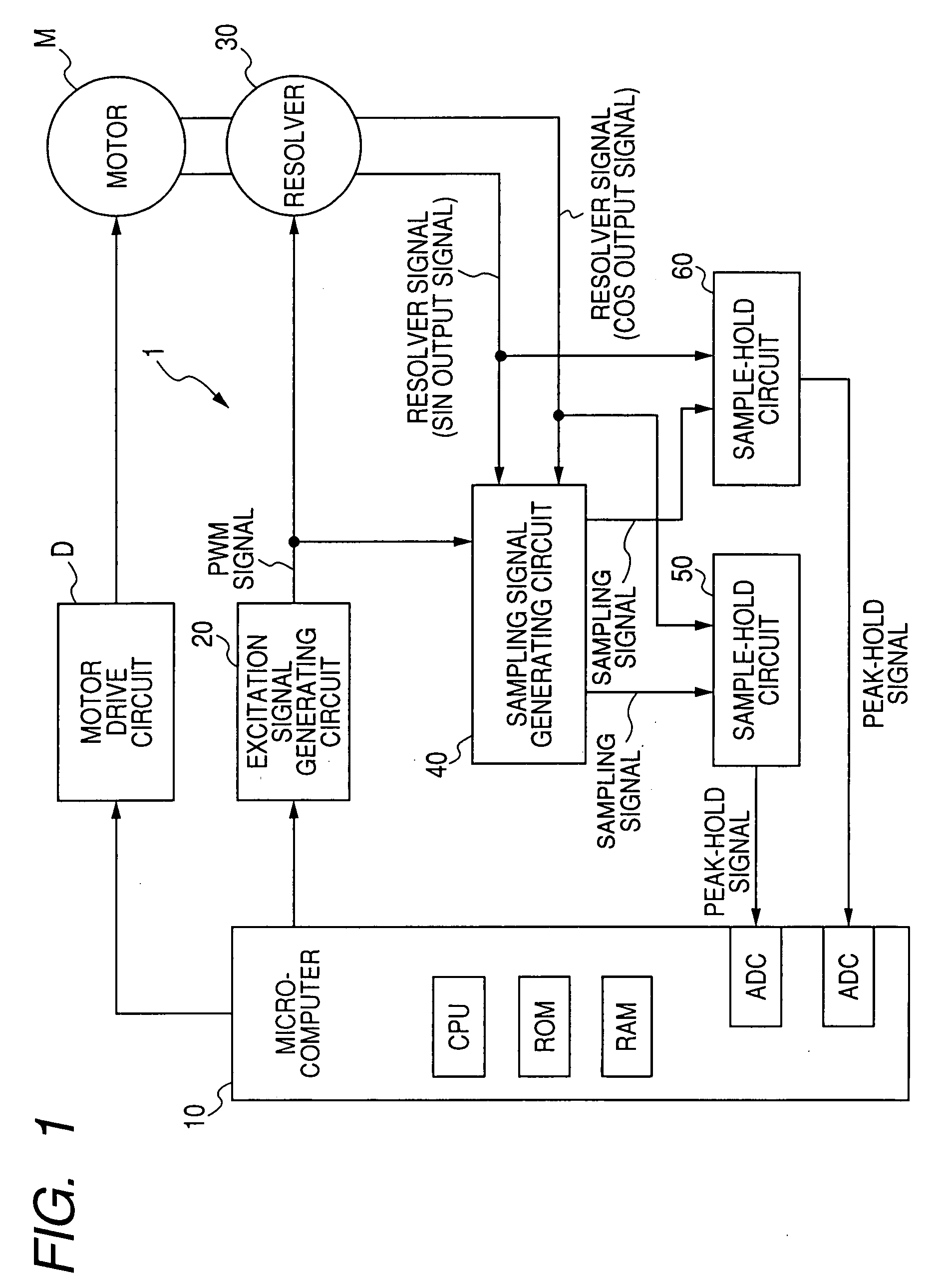
[0045]FIG. 1 is a block diagram showing an overall structure of a rotation angle detection apparatus 1 according to an embodiment of the invention.

[0046]The rotation angle detection apparatus 1 includes a microcomputer 10, an excitation signal generating circuit 20, a resolver 30, a sampling signal generating circuit 40, and sample-hold circuits 50, 51.

[0047]The microcomputer 10, which includes therein a CPU, a ROM, a RAM and A / D converters, performs a process of outputting a PWM signal (Pulse Width Modulation signal) used for generating a sinusoidal excitation signal to the excitation signal generating circuit 20, a process of capturing a peak-hold value of a resolver signal from the sample-hold circuit 50 through the A / D converter, and a process of computing a rotation angle of a motor M on the basis of the captured peak-hold value of the resolver signal. Although the microcomputer 10 also performs a process of driving the motor M through a motor drive circuit D, explanation on th...


PUM


Abstract

The rotation angle detection apparatus for detecting a rotation angle of a rotating body on the basis of a resolver signal outputted from a resolver mounted on the rotating body includes a first function of detecting a specific phase timing of the resolver signal, a second function of measuring a time needed for the resolver signal to reach from the specific phase timing to a peak thereof, a third function of generating a sampling timing in accordance with the time measured by the second function, a fourth function of sample-holding the resolver signal at the sampling timing to hold a peak value of the resolver signal, and a fifth function of computing the rotation angle of the rotating body on the basis of the peak value of the resolver signal held by the fourth function.

Description

CROSS-REFERENCE TO RELATED APPLICATION[0001]This application is related to Japanese Patent Application No. 2006-300393 filed on Nov. 6, 2006, the contents of which are hereby incorporated by reference.BACKGROUND OF THE INVENTION[0002]1. Field of the Invention[0003]The present invention relates to an apparatus and a method for detecting a rotation angle of a rotating body by use of a resolver.[0004]2. Description of Related Art[0005]An electric-driven steering apparatus, which is one of important parts of a vehicle, is required to have a high reliability. Accordingly, it has been proposed to use a rotation angle detection apparatus using a resolver that has a high mechanical reliability for the purpose of detecting a steering torque of an electric-driven steering apparatus and a rotation position of an electric motor thereof. For example, refer to Japanese Patent Application laid-open No. 2003-166803. Such a rotation angle detection apparatus has a configuration that an excitation si...

Claims


Application Information

Patent Timeline
Patent Type & Authority Applications(United States)
IPC IPC(8): G05B1/06H02K24/00
CPCG01D5/208G01D5/2073G01P3/46G01P3/481
Inventor KOSAKA, SHINYAMAMOTO, TOSHIHISAHAYASHI, YOSHITAKAURA, YOSHIYUKI
Owner DENSO CORP
Why Eureka
Try Eureka