Microcomputer and motor control system provided therewith

a technology of motor control system and microcomputer, which is applied in the direction of program control, dynamo-electric converter control, instruments, etc., can solve the problems of low position accuracy and limited time when the motor can be controlled, and achieve the effect of high accuracy

Inactive Publication Date: 2012-07-03
KK TOSHIBA
View PDF12 Cites 5 Cited by
  • Summary
  • Abstract
  • Description
  • Claims
  • Application Information

AI Technical Summary

Benefits of technology

[0011]Therefore, an object of the present invention is to provide a microcomputer having a function of fast converting an output signal of the resolver without dependence upon software, and a motor control system provided with the microcomputer.
[0013]According to the above-described microcomputer, the position data detected by the resolver can be parallel transferred via an inner bus to a CPU fast since the digital signal converter of the resolver is mounted on the single chip. Furthermore, processing load of the CPU used for signal conversion in JP-A-2005-114442 can be reduced, and a relatively sufficient processing capacity can be distributed to other control. Consequently, a high-accurate motor can be realized.
[0015]According to the above-described motor control system, the motor can be driven with high accuracy when controlled in a high-speed range using the resolver.

Problems solved by technology

However, an angle detected by the Hall element and indicative of a rotor position is coarse such that a position accuracy is low.
This results in a problem that a time when the motor can be controlled is limited except for a period of execution of a position detection processing.

Method used


Image

  • Microcomputer and motor control system provided therewith
  • Microcomputer and motor control system provided therewith
  • Microcomputer and motor control system provided therewith

Examples


Embodiment Construction

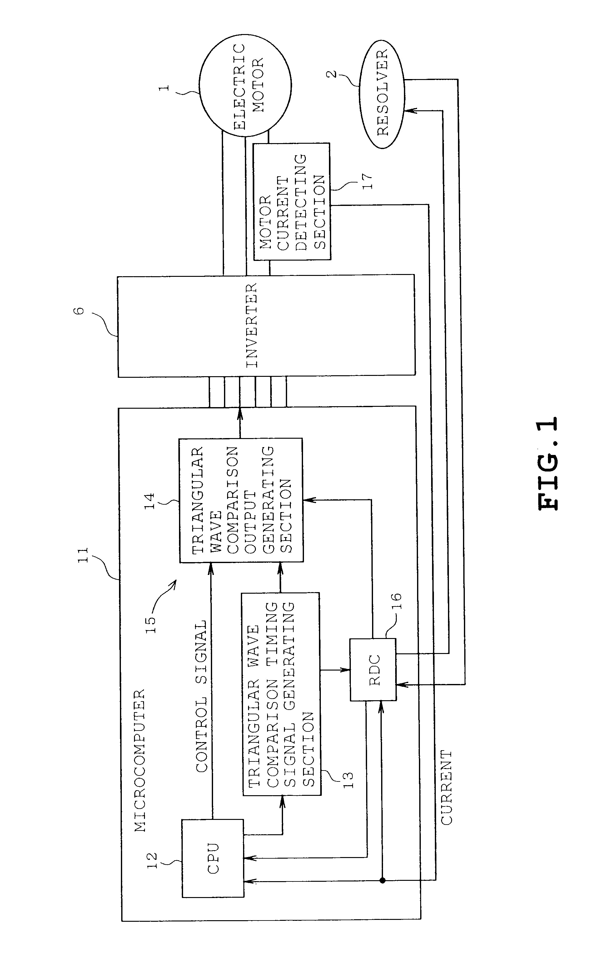
[0021]A first embodiment will be described with reference to FIGS. 1 to 3B. In FIGS. 1 to 3B, identical or similar parts are labeled by the same reference symbols as those in FIG. 5 and the description of these parts is eliminated. Only the differences will be described in the following. A motor control system of the first embodiment comprises a microcomputer 11 (a motor control circuit 11) having a function corresponding to the RDC 3 except for the RDC 3 and the microcomputer 4 as shown in FIG. 5.

[0022]The microcomputer 11 comprises a single semiconductor chip on which are mounted a pulse-width-modulation (PWM) signal output section 15 composed of a central processing unit (CPU) 12, a triangular wave comparison timing signal generating section 13 (carrier wave output section; and hereinafter, “timing signal generating section”), and a digital signal converter 16 (RDC). Thus, the microcomputer 11 is configured into a one-chip microcomputer. An electric motor 1 may be a spindle motor...


PUM


Abstract

A microcomputer which obtains a rotor position signal from a biphase signal delivered by a resolver mounted on an electric motor according to a rotation phase of a rotor relative to a stator, thereby controlling the motor based on the rotor position signal. The microcomputer includes a digital signal converter which is configured by hardware and converts the biphase signal delivered from the resolver into a digital data position signal, the digital signal converter being mounted on a single chip.

Description

CROSS-REFERENCE TO RELATED APPLICATIONS[0001]This application is based on and claims the benefit of priority from the prior Japanese Patent Application No. 2008-181347, filed on Jul. 11, 2008, the entire contents of which are incorporated herein by reference.BACKGROUND[0002]1. Field[0003]The present invention relates to a microcomputer which obtains a rotor position signal from a biphase signal delivered from a resolver mounted on an electric motor, and a motor control system provided with the microcomputer.[0004]2. Related Art[0005]Low-cost position sensitive detectors such as a Hall element need to be disposed at a predetermined location of an electric motor to detect a rotor position in order that a brushless DC motor may be driven. However, an angle detected by the Hall element and indicative of a rotor position is coarse such that a position accuracy is low. In particular, when the Hall element is used for sinusoidal drive which necessitates a high accurate position detection, ...

Claims


Application Information

Patent Timeline
Patent Type & Authority Patents(United States)
IPC IPC(8): G05B19/29G01D5/245H02P6/06H02P6/16H02P6/08
CPCG01D5/2451G11B19/28H02P6/165H02P6/17
Inventor HASEGAWA, YUKIHISAHARA, TAKEHIRO
Owner KK TOSHIBA
Why Eureka
Try Eureka