Sealed lamp device and projector

a technology of sealed lamp and projector, which is applied in the direction of discharge tube main electrode, incadescent cooling arrangement, instruments, etc., can solve the problems of increasing the number of components and the size of the projector, severe damage to the product value of the projector, and increasing the cost of the projector, so as to improve the radiation performance of the sealed lamp device, the effect of reducing the cost and improving the radiation performan

Inactive Publication Date: 2008-05-08
SONY CORP
View PDF5 Cites 6 Cited by
  • Summary
  • Abstract
  • Description
  • Claims
  • Application Information

AI Technical Summary

Benefits of technology

[0016] The projector may have a larger sealed volume occupied by the discharge lamp burner, and vertical air convection may flow to the entire inner wall of the hollow casing structure by the flow-guiding plate. Accordingly, the radiation performance may be improved. The projector may be made in lower cost while being a compact structure.
[0017] According to the present invention, the radiation performance of the sealed lamp device may be improved. With this improvement, temperature range of the sealed lamp device may be regul

Problems solved by technology

However, as a result of the changes, a unacceptable level of air blowing noise may be generated, thereby severely damaging product value of a projector.
Although there is a sealed lamp device that is provided with a

Method used


Image

  • Sealed lamp device and projector
  • Sealed lamp device and projector
  • Sealed lamp device and projector

Examples


Embodiment Construction

[0025] Detailed description of an embodiment of the present invention will be made in accordance with the drawings as below.

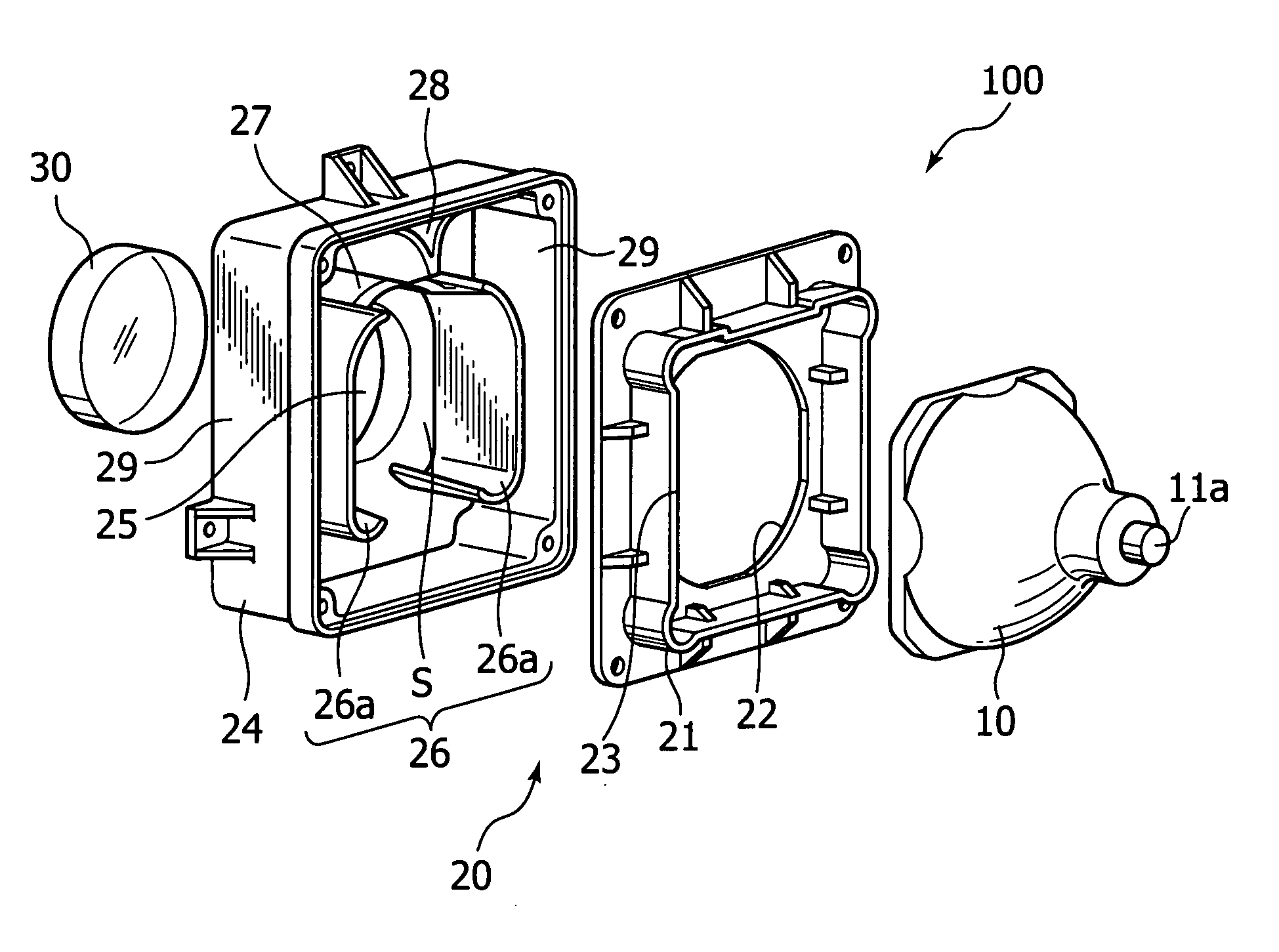
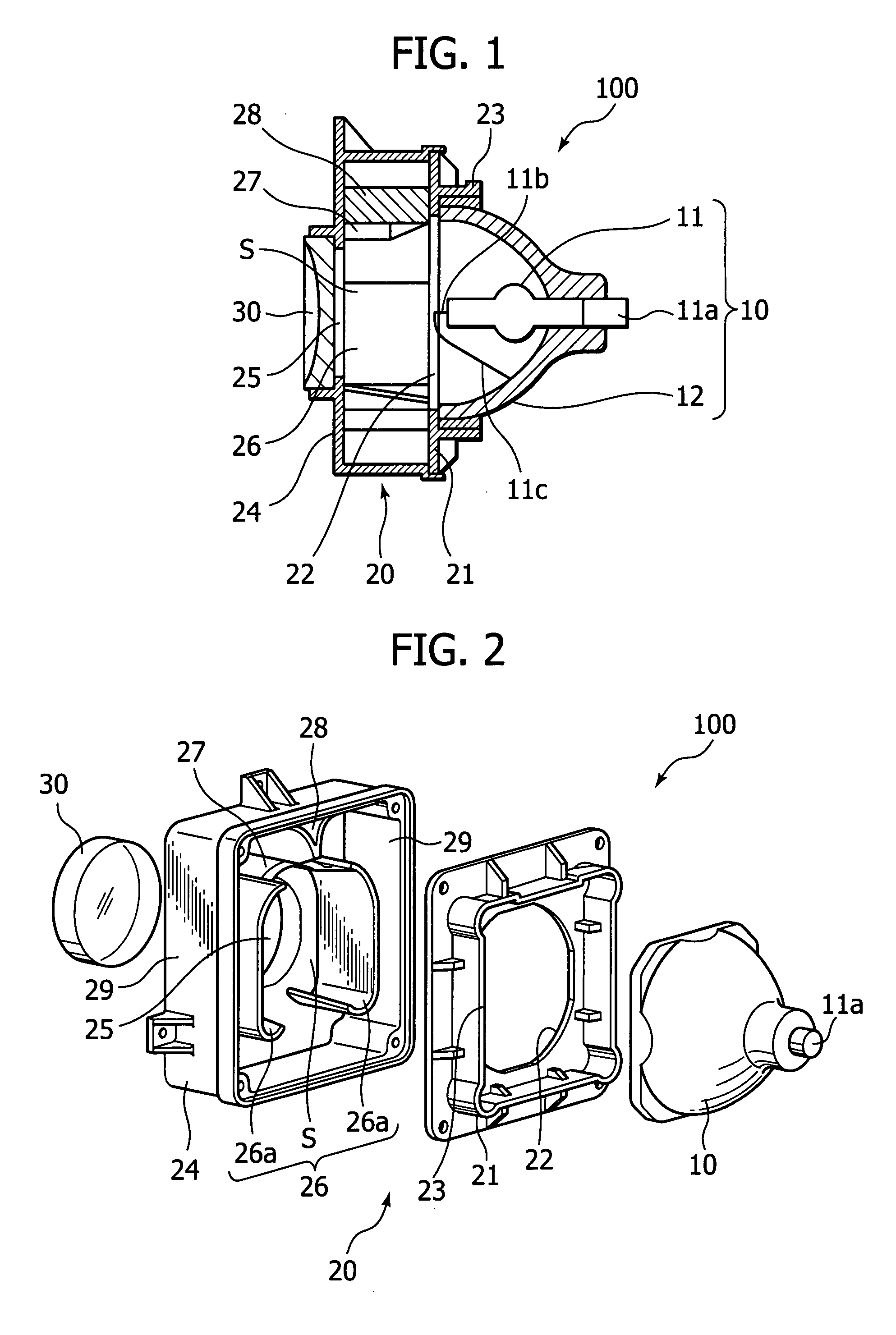
[0026]FIG. 1 is a section view showing a sealed lamp device of an embodiment of the present invention, and FIG. 2 is a exploded perspective view showing the sealed lamp device shown in FIG. 1.

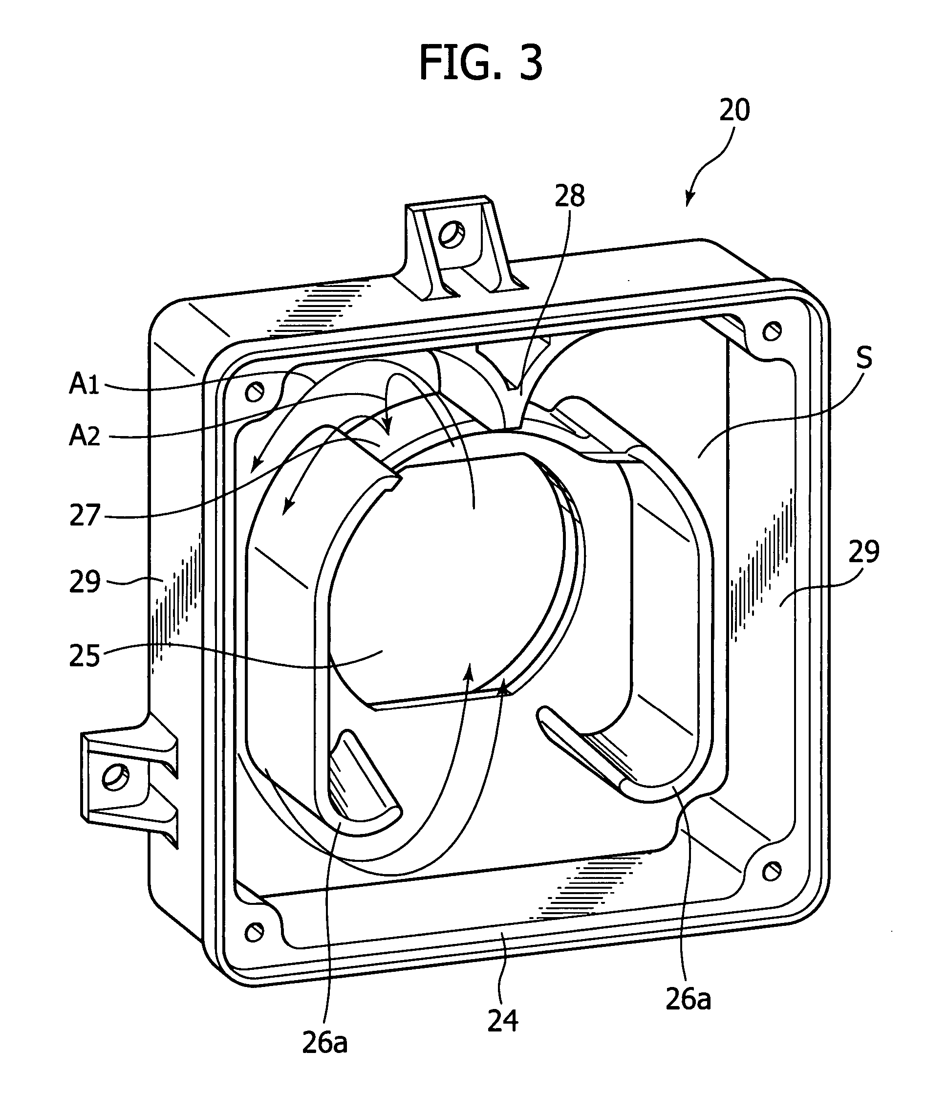
[0027] In FIG. 1, a sealed lamp device 100 includes a lamp unit 10 including: a discharge lamp burner 11 as a lighting source and a concave mirror 12 which is formed in a bowl shape and reflects radiation light of the discharge lamp burner 11; a hollow casing structure 20 disposed in a front side of the concave mirror 12 and having an opening section in the front side; and a front plate 30 made of transparent material such as lens, glass and resin, closing the opening section of the hollow casing structure 20 and emitting radiation light of the discharge lamp burner 11.

[0028] The discharge lamp burner 11 uses a DC starting system and is horizontally held inside the conc...


PUM


Abstract

A sealed lamp device may include a discharge lamp burner; a concave mirror opened to a front direction and reflecting radiation light of the discharge lamp burner to the opened side, an optical axis of the concave mirror being aligned with an optical axis of the discharge lamp burner; a hollow casing structure having an opening section in a front side, to which the concave mirror opened out; and a front plate closing the opening section of the hollow casing structure and emitting the radiation light. The hollow casing structure may be made wider than an opening width of the concave mirror, so as to increase a sealed volume occupied by the discharge lamp burner.

Description

CROSS-REFERENCE TO RELATED APPLICATIONS [0001] This application claims priority from Japanese Patent Application No. JP 2006-254815 filed in the Japanese Patent Office on Sep. 20, 2006, the entire content of which is incorporated herein by reference. BACKGROUND OF THE INVENTION [0002] 1. Field of the Invention [0003] The present invention relates to a sealed lamp device such as a metal halide lamp which is one type of high voltage discharge lamps, and a projector using the same. [0004] 2. Description of Related Art [0005] In related art, a light source unit configured by combining a concave mirror and a discharge lamp burner such as an extra-high pressure mercury lamp and a metal halide lamp is used as a lighting source for a projector. [0006] Recently, a so-called sealed lamp device, in which a front plate made of a translucent material is placed at a front opening of the concave mirror on the light-emitting side, is typically used. [0007] The discharge lamp burner radiates not onl...

Claims


Application Information

Patent Timeline
IPC IPC(8): G03B21/16H01J5/16H01J7/24
CPCG03B21/16H01J61/86H01J61/52H01J61/025
Inventor YAMAOKA, KEIHAGA, MOTOHISATERASAKI, KAZUYAYAMASHITA, KATSUHIRONASU, TAKASHI
Owner SONY CORP
Why Eureka
Try Eureka