
Alignment Information Display Method And Its Program, Alignment Method, Exposure Method, Device Production Process, Display System, Display Device, And Program And Measurement/Inspection System

a technology of alignment information and display method, which is applied in the field of alignment information display method and its program, exposure method, exposure method, display system, etc., can solve the problems of falling overall yield and deteriorating characteristics of circuit formation, and achieve high quality, high precision positioning, and good overlay accuracy

Active Publication Date: 2008-05-08
NIKON CORP
View PDF23 Cites 48 Cited by
  • Summary
  • Abstract
  • Description
  • Claims
  • Application Information

AI Technical Summary

Benefits of technology

[0018]An object of the present invention is to provide an alignment information display method, alignment information display program, display device, and display program enabling efficient analysis or evaluation of data of measurement results for the results of actual alignment and as a result enabling effective alignment conditions or parameters to be set.
[0019]Further, another object of the present invention is to provide an alignment method enabling high precision positioning using effective alignment conditions and parameters set based on the measurement results for the actual alignment results.

Problems solved by technology

Therefore, if the overlay accuracy between layers is poor, the characteristics of the circuits formed deteriorate.
In the worst case, the semiconductor devices become defective and the overall yield ends up falling.

Method used


Image

  • Alignment Information Display Method And Its Program, Alignment Method, Exposure Method, Device Production Process, Display System, Display Device, And Program And Measurement/Inspection System
  • Alignment Information Display Method And Its Program, Alignment Method, Exposure Method, Device Production Process, Display System, Display Device, And Program And Measurement/Inspection System
  • Alignment Information Display Method And Its Program, Alignment Method, Exposure Method, Device Production Process, Display System, Display Device, And Program And Measurement/Inspection System

Examples


Embodiment Construction

[0073]An embodiment of the present invention will be explained with reference to FIG. 1 to FIG. 23.

[0074]In the present embodiment, an exposure system having exposure apparatuses and an alignment data evaluation system will be illustrated to explain the present invention.

[0075]Exposure System

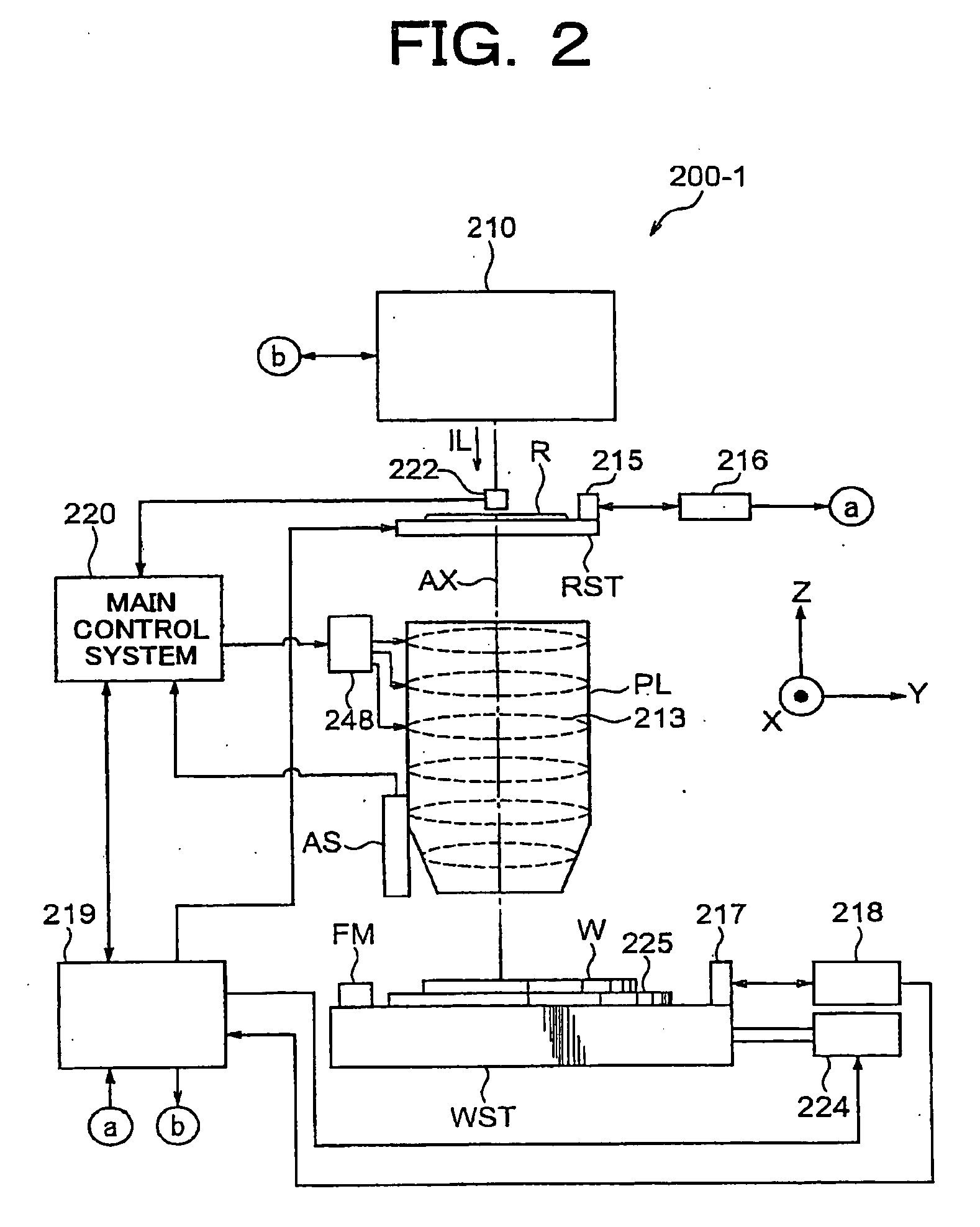
[0076]First, the overall configuration of the exposure system of the present embodiment will be explained with reference to FIG. 1 to FIG. 3.

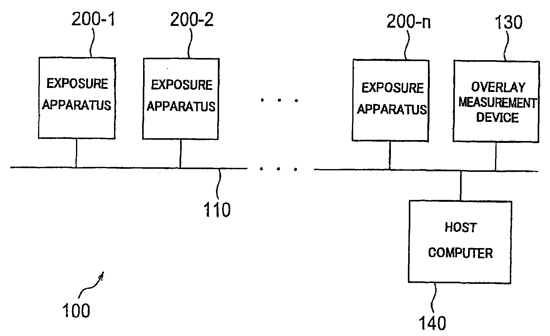
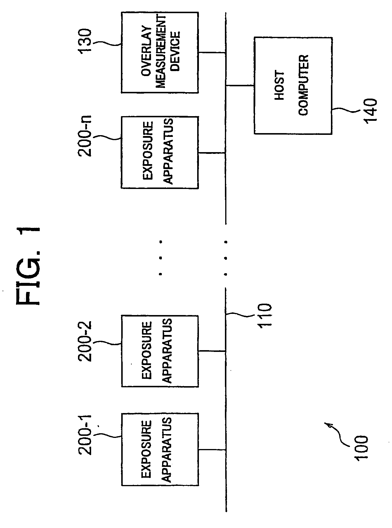
[0077]FIG. 1 is a view showing the overall configuration of the exposure system 100 according to the present embodiment.

[0078]As shown in FIG. 1, the exposure system 100 has N number of exposure apparatuses 200-1 to 200-n, an overlay measuring device 130, and a host computer 140. These devices are connected by a LAN 110 to enable transfer of data between each other. Note that the LAN 110 may further have other processing devices, measuring devices, computers, etc. connected to it to enables transfer of data.

[0079]Each exposure apparatus 200-i (i=1 to n) (he...


PUM


Abstract

[PROBLEM] To provide an information display method enabling efficient analysis and evaluation of alignment results and thereby facilitating the setting of effective alignment conditions or parameters.[MEANS FOR SOLUTION] The alignment information display method of the present invention receives as input the data of the results of processing relating to alignment measurement, receives as input information relating to the parameters of the alignment measurement, finds the information for display from the data of the results of processing based on the input parameters, and displays the found desired information for display by a display mode by which the effects on the alignment measurement become clear. Therefore, in setting the desired conditions, it is possible to easily confirm the results of analysis by the set conditions, that is, the effects of the set conditions. Therefore, a user can easily detect the optimum alignment conditions and parameters.

Description

TECHNICAL FIELD[0001]The present invention relates to alignment processing performed in a lithography process when producing, for example, a semiconductor device, liquid crystal display device, CCD, or other imaging device, plasma display device, thin film magnetic head, or other electronic device (hereinafter simply referred to as an “electronic device”), more particularly relates to an alignment information display method, alignment information display program, display device, and program relating to that display for displaying information relating to the alignment processing in a desired mode so as to enable suitable, easy setting of conditions, parameters, etc. for measurement of alignment and a measurement / inspection system for outputting data provided for such a display. Further, it relates to an adjustment method for determining the position of the wafer etc. by the conditions and parameters set based on the displayed information, an exposure method for exposure by alignment ...

Claims


Application Information

Patent Timeline
IPC IPC(8): G03B27/42G06F15/00H01L21/027
CPCG03F7/70633G03F9/7003H01L21/682G03F9/7092G03F9/7046Y02P90/80G05B15/00
Inventor OKITA, SHINICHI
Owner NIKON CORP
Learn More