Multiple access apparatus and method using power line

a multi-access apparatus and power line technology, applied in the field of signal superimposed, can solve the problems of limited time division telecommunication methods, limited telecommunication methods, and inability to enable simultaneous access, so as to increase telecommunication transmission capacity, and ensure the effect of security

Active Publication Date: 2008-05-08
SHONAN INSTITUTE OF TECHNOLOGY +2
View PDF2 Cites 11 Cited by
  • Summary
  • Abstract
  • Description
  • Claims
  • Application Information

AI Technical Summary

Benefits of technology

[0066]The present invention is contrived to not only secure a large number of channels allowing a simultaneous use, but also allow a use of a time division telecommunication at the same time in a power line telecommunication network system, thereby enabling an increase in a telecommunication transmission capacity between individual service outlets as compared to the conventional method. Also enabled is a capability of securing a sufficient level of security for managing and operating a networked electrical appliances, a management system used for a coin-operated laundry, an unmanned shop, et cetera, because the code division multiple access namely uses a different code for each channel as a simple encoding key in encoding a signal of each channel and superposing on one another, followed by the receiving end demodulating a signal of a required channel by using the encoding key thereof. There is a possibility of theft of important information from a radio wave transmitted from a portable phone, radio communication equipment, et cetera, such security, however, is secured by a control and telecommunication by way of a network system provided by the present invention.
[0067]A use of the power line telecommunication makes it possible to increase a telecommunication transmission capacity between each service outlet and therefore the present invention is empowered to constitute a backbone technique for a power line telecommunication part in building up a ubiquitous society by using an optical, radio wave, power line telecommunications.

Problems solved by technology

In spite of the fact that networks, such as the Internet, utilizing indoor power line have actually been built up in Europe and America, little progress has been made in a development of a multiple channel code division multiple access type enabling a high speed simultaneous access of a plurality of terminals.
This method has only been capable of a time division telecommunication.
For example, although a method of transmitting packetized data after confirming that other equipment performing an information and telecommunication on a power line, such as a Carrier Sense Multiple Access (CSMA) is adopted by many standards and products, a simultaneous access has not been enabled.
As for other methods other than a random access, the considered as a multiple access system includes a frequency division multiple access (FDMA), a time division multiple access (TDMA); the frequency division multiple access (FDMA) type, however, is not suitable to a power line telecommunication in which a characteristic is widely different depending on a frequency.
As for the TDMA type, it has been conventionally believed to be very difficult to accomplish it in a power line environment because the TDMA requires a common clock among each station.
However, it has been difficult to accomplish a many-to-many simultaneous access in a power line telecommunication by the CDMA.
However, in the case of multiplexing a signal by applying a spectrum diffusion system, the receiving side is not capable of generating a pulse signal anew, as in the case of the PCM system.
The distortion of the waveform on the time axis at the time of receiving a signal is actually a large issue of the spectrum diffusion system and CDMA.
There is accordingly a known fact that a phase, et cetera, of the information signal is changed by a certain filter which is formed by the connection transformer and AC power line, thus giving a waveform distortion to the superimposed information signal.
Even if such a waveform distortion is generated in an information signal, however, it has not caused a fundamental obstacle to the above noted control signal or analog signal because of the characteristic of a signal process, nor has it caused a difficulty to a digital signal used in the PCM system, to the extent of being incapable of repairing a code error due to a waveform distortion by means of a signal reproduction process on the reception side, and therefore a system level problem has not occurred.
However, if an information signal multiplexed according to the CDMA is attempted to transmit by the above noted power line communication system, a problem of an inability of demodulating the information signal arises because an inverse diffusion on the reception side becomes difficult due to a waveform distortion of the information signal.
That is, the power line communication system using a power signal of an AC power line as carrier wave and superimposing an information signal on the power signal is incapable of superimposing the information signal of a desired waveform without a waveform distortion, and therefore a problem of being unable to transmit the information signal by the CDMA occurs.
Furthermore, the above noted patent documents do not provide either (1) how to synchronize each code signal or (2) a method for forming a code multiplex signal both of which are the most important problems in accomplishing the CDMA for general uses including a portable phone in order to form a code multiplex signal from a synchronous signal on a power line and independent signals from individual service outlets and superimpose the code multiplex signal on the power line.

Method used


Image

  • Multiple access apparatus and method using power line
  • Multiple access apparatus and method using power line
  • Multiple access apparatus and method using power line

Examples


embodiment 1

[0247]FIG. 13 exemplifies a connection between a transmission unit and a reception unit by one circuit in a model for simulating a code division multiple access (CDMA) for accomplishing a digital signal process (DSP). In an actual line, not only a power line but also any line has a resident noise component, influencing a telecommunication.

[0248]However, it is a model validating by a simulation that a use of the CDMA system becomes hardly influenced by a noise component.

[0249]FIG. 14 is a diagram showing an internal model of a code division multiplex (CDMA) transmission unit, indicating an internal configuration of a TXCODE 131 shown in FIG. 13. The CH1 through CH4 shown in FIG. 14 respectively generate CDMA signals, receive synchronous signals input from in1 through in4, adjust gains, et cetera, of the generated signal and transmit from individual outputs CH1 (−1), CH1 (1), CH2 (−1), CH2 (1), CH3 (−1), CH3 (1), CH4 (−1) and CH4 (1), respectively. Triangles shown by the numerical 141...

embodiment 2

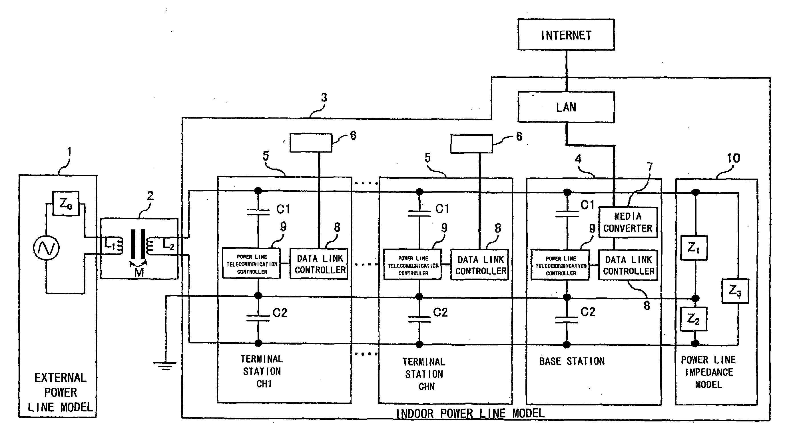
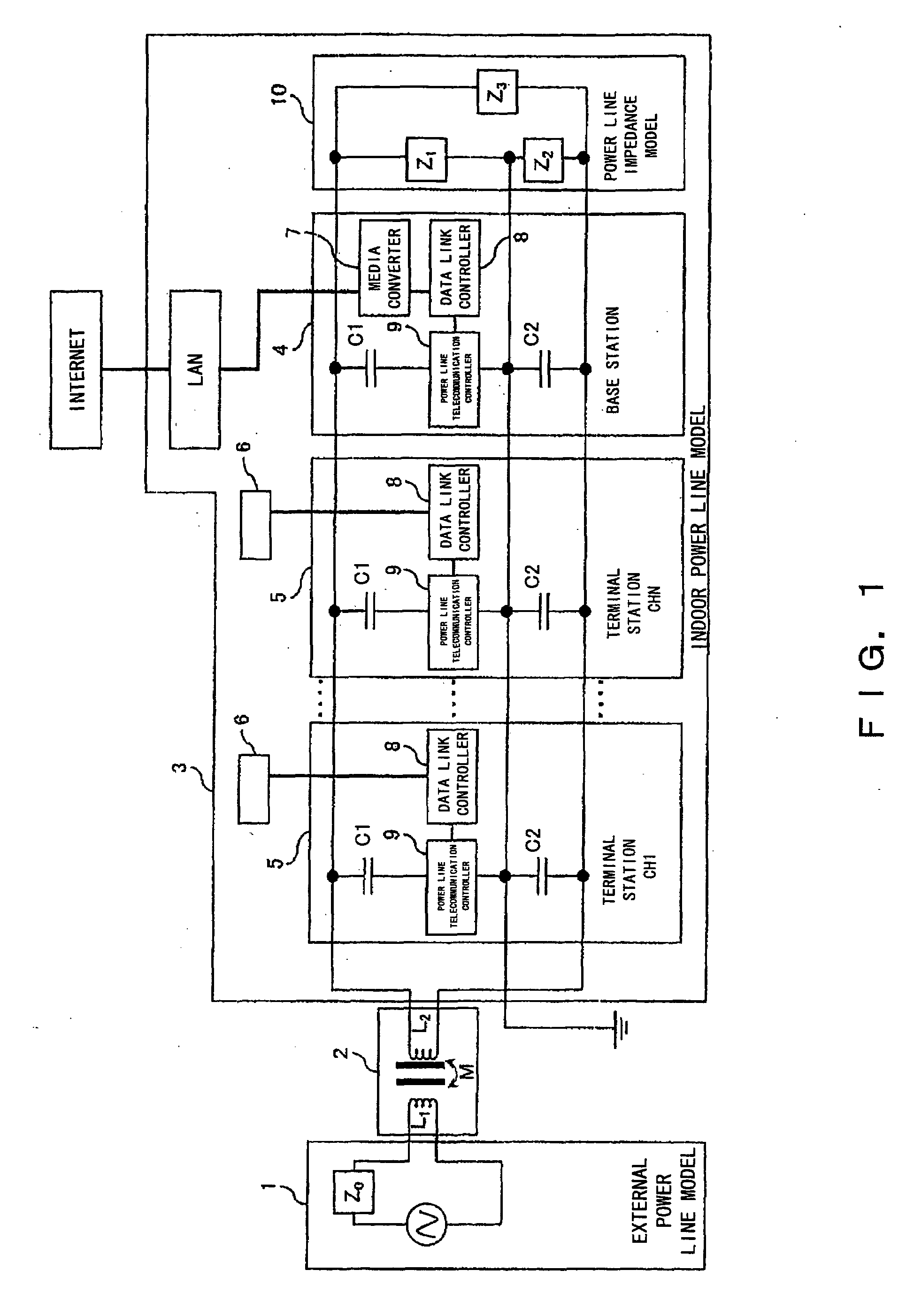
[0255]FIG. 17 is a model equipping a power line model in a CDMA model line shown in FIG. 12. And the present model is an original type model of a same clock time code division multiple telecommunication enabling an uplink connection to a base station from a terminal station connecting to an individual service outlet also considering an influence of a distribution constant of a power line to a power line impedance environment and a current signal superimposing-type code division multiple telecommunication (access) simulation.

[0256]An AC power supply 1 is connected to the primary side of a step-down transformer 170 of the present model for supplying a power signal (e.g., 100 volts, 50 Hz or 60 Hz, et cetera).

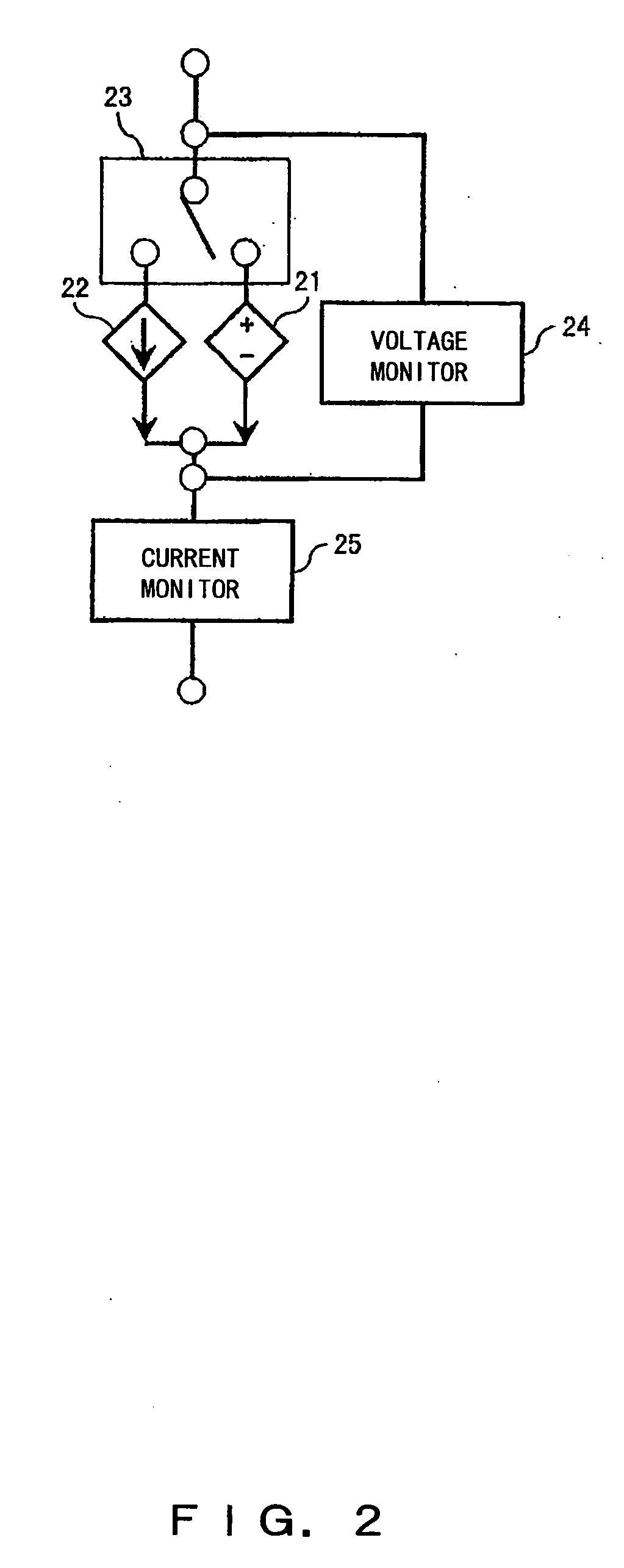
[0257]A terminal station in the present model is constituted by model DIPs 176a through 176d (i.e., a dependent current source) for superimposing a signal transmitted from each channel of a TXCODE 175 on a current signal of the power line, a monitor signal conversion block 177a th...

embodiment 3

[0263]FIG. 19 is a power line impedance environment and a current signal superimposing-type code division multiple telecommunication (access) simulation, which is a downlink connection from a base station to an individual terminal station (the present embodiment does not consider a distribution constant-wise influence of a power line; while a synchronous signal uses a simplified model).

[0264]Likewise at the time of an uplink, a connection of an AC power source on the primary side of a step-down transformer 170 of the present model supplies a power signal (e.g., 100 volts, 50 Hz or 60 Hz, et cetera). A terminal station in the present model is constituted by a model DVP 191 (i.e., a dependent voltage source) for superimposing a signal transmitted from each channel from a TXCODE 199 on a voltage signal of the power line, by a voltage monitor signal conversion block 192, by a current monitor signal conversion block 193 and by a capacitor 194; and a transmission signal is transmitted fro...


PUM


Abstract

Provided is a telecommunication apparatus and a telecommunication method accomplishing a one-to-many, many-to-one, and many-to-many simultaneous accesses in a power line telecommunication of a code division multiple access (CDMA) by using an AC power line (including the ground).A comprisal includes an external power line model 1, a power distribution board 2 and an indoor power line model 3 which is connected to a power line by way of a capacitor for shutting off a sine wave of a power signal of a low frequency; a terminal station 5 and a base station 4 perform a power line telecommunication by way of a plug outlet; and the terminal station 5 controls and manages electric appliances installed in the indoor power line model 3. The terminal station 5 and base station 4 which are connected to the power line are connected to the Internet by way of a line; the base station 4 comprises a media converter 7 and a data link controller 8 which are connected to an external data bus, and also a power line telecommunication controller 9 for controlling a transmission and reception of an information signal and a synchronous signal; the terminal station 5 comprises a power line telecommunication controller 9 for controlling a transmission and reception of an information signal and a synchronous signal, thereby accomplishing an apparatus and method for carrying out a power line telecommunication.

Description

BACKGROUND OF THE INVENTION[0001]1. Field of the Invention[0002]The present invention relates to a signal superimposing apparatus and a signal superimposing method which use a power signal of an alternate current (AC) power line as a carrier wave for use in a power line communication for transmitting an information signal, and in particular to a telecommunication apparatus and a telecommunication method which enable a telecommunication between a base station and a terminal station through a power line forming a many-to-many multiple access network of a code division multiple access type.[0003]2. Description of the Related Art[0004]Today, a power line communication (PLC) is considered to be effective as one of information transmission means for building up a ubiquitous society, which requires a very large transmission capacity and speed. In spite of the fact that networks, such as the Internet, utilizing indoor power line have actually been built up in Europe and America, little prog...

Claims


Application Information

Patent Timeline
Patent Type & Authority Applications(United States)
IPC IPC(8): H04J13/00
CPCH04B1/707H04B3/542H04B2203/5408H04B2203/5495H04B2203/5425H04B2203/5445H04B2203/5416
Inventor OKAZAKI, HIDEAKIKAWAMOTO, TAKUJI
Owner SHONAN INSTITUTE OF TECHNOLOGY
Why Eureka
Try Eureka