Slicer circuit capable of judging input signal correctly

a circuit and input signal technology, applied in the field of circuits, can solve problems such as noise interference in circuits and errors in judging signals, and achieve the effect of delay the up-shift or down-shift speed of differential-mode signals

Inactive Publication Date: 2008-05-08
WINBOND ELECTRONICS CORP
View PDF1 Cites 18 Cited by
  • Summary
  • Abstract
  • Description
  • Claims
  • Application Information

AI Technical Summary

Benefits of technology

[0012]To achieve the aforementioned or other objectives, the present invention provides a slicer circuit which has the feature that a counting-circuit is employed to count the number continuous times of signals in a same level continuous outputted from the comparator thereof, and the number of con

Problems solved by technology

Consequently, the duty ratio of the digital output varies larger or smaller, which further influences the post-stage digital signal processing (DSP), produces error bits and results in errors of ju

Method used


Image

  • Slicer circuit capable of judging input signal correctly
  • Slicer circuit capable of judging input signal correctly
  • Slicer circuit capable of judging input signal correctly

Examples


Embodiment Construction

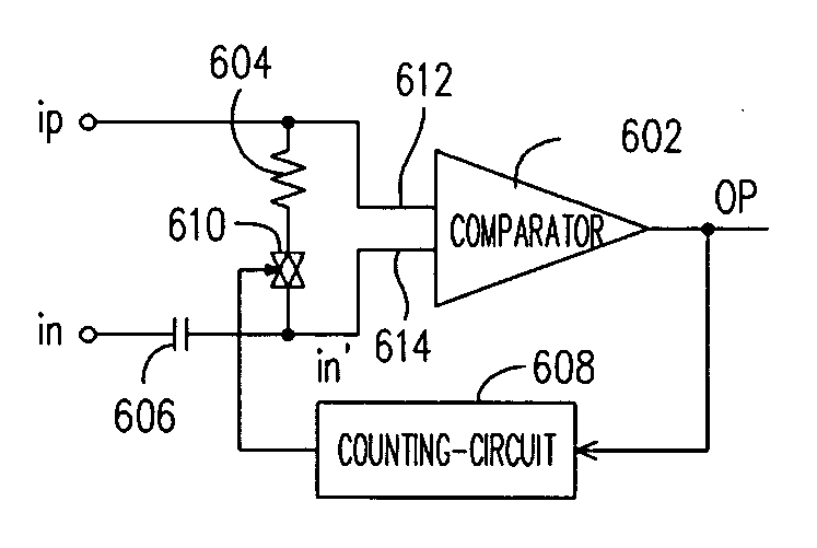
[0023]FIG. 6 is a schematic drawing of a slicer circuit according to an embodiment of the present invention. Referring to FIG. 6, the slicer circuit includes a comparator 602, a resistor 604, a capacitor 606, a counting-circuit 608 and a switch 610. Wherein, an end of the resistor 604 is coupled with the first input terminal 612 of the comparator 602 and a first modulation signal ip, while another end of the resistor 604 is coupled with the second input terminal 614 of the comparator 602 via the switch 610. The second input terminal 614 of the comparator 602 is coupled with a second modulation signal in via the capacitor 606 and the output OP of the comparator 602 is coupled with the input of the counting-circuit 608. The resistor 604 and the switch 610 can be formed by an MOS (metal oxide semiconductor) active device at least, respectively. In the embodiment, the output of the counting-circuit 608 is coupled with the switch 610.

[0024]The first modulation signal ip and the second mo...


PUM


Abstract

A slicer circuit is disclosed. The slicer circuit has the feature that a counting-circuit is employed to count the number of continuous times of signals in a same level continuous outputted from the comparator thereof, and when the number of continuous times reaches a preset value, a control signal is output to make a resistance circuit consisting of dynamic devices open, so as to largely delay the up-shift or down-shift speed of an input DC reference level and enable the slicer circuit to continue to judge the input signal correctly according to the input DC reference level.

Description

BACKGROUND OF THE INVENTION[0001]1. Field of Invention[0002]The present invention relates to a slicer circuit, and more particularly, to a slicer circuit employing a counting-circuit.[0003]2. Description of the Related Art[0004]In a mobile communication system (MCS), a data slicer counts as a part of a data-recovery circuit to convert an analog data signal into a digital data signal. The signal input manner of a slicer circuit is mainly categorized into two kinds: input of single-ended modulation signal and input of dual-ended differential-mode modulation signal.[0005]FIG. 1 is a schematic drawing of a conventional slicer circuit for inputting single modulation signals. The slicer circuit of FIG. 1 includes a comparator 102, a resistor 104 and a capacitor 106. Wherein, an input terminal of the comparator 102 is coupled with a modulation signal ip, while another input terminal is coupled with the modulation signal ip via the resistor 104. The capacitor 106 is used to make the node co...

Claims


Application Information

Patent Timeline
IPC IPC(8): H04L25/06H04L25/10
CPCH04L25/061
Inventor CHENG, YUCHEN, YI-KUANFAN, CHUN-WAH
Owner WINBOND ELECTRONICS CORP
Why Eureka
Try Eureka