Pulse Width Modulation Or Variable Speed Control Of Fans In Refrigerant Systems

a technology of variable speed control and fan, which is applied in the direction of lighting and heating apparatus, process and machine control, instruments, etc., can solve the problems of significant evaporator and overall system performance degradation, improper heat exchanger orientation, and possible refrigerant maldistribution, etc., and achieve uniform heat transfer rate

Inactive Publication Date: 2008-05-15
CARRIER CORP
View PDF7 Cites 23 Cited by
  • Summary
  • Abstract
  • Description
  • Claims
  • Application Information

AI Technical Summary

Benefits of technology

[0011]In accordance with one embodiment of the invention, precise control of the airflow distribution over the heat exchangers is accomplished by utilizing a variable speed fan. The use of a variable speed fan becomes especially advantageous when two or more fans are utilized to move the air through the heat exchanger. In this case, for example, one fan can be of a variable speed type (controlled by a variable speed drive) while the other fan is of a fixed speed design. By controlling the speed of the variable speed fan, the airflow distribution over the heat exchanger can be controlled in such a fashion that all sections of the heat exchanger receive the adequate and optimal airflow. Other options are possible, where two or more fans dedicated to a particular heat exchanger are of a variable speed design. In this embodiment, the speed of the variable speed fans can be controlled simultaneously or independently to achieve the desire airflow distribution over the heat exchanger surfaces to obtain a desired heat transfer rate. The algorithm for operation of the variable speed fans can be selected during the development testing or can be adjusted in the factory after the unit has been built to account for variations in the unit design as well as various options and features. The final adjustments can also be made in the field, if the air maldistribution over the heat exchanger surfaces is found to be application or installation dependent. This embodiment also allows for component standardization and a reduced number of spare parts. The fan speed control logic can be also adjusted in accordance to the operating conditions to cover a wide spectrum of applications and an entire operating envelope.
[0012]In accordance with a second embodiment of the invention, improved airflow distribution in the heat exchangers is accomplished through the use of fans operating in pulse width modulation mode. This can be achieved by rapidly switching fans from high to low speed, if it is a two-speed fan, or simply turning the fan on and off, if it is a single-speed fan design. Also, when the fan is operating at a reduced speed or is turned off, it consumes less power, or no power respectively, thus potentially improving system efficiency. The amount of time the fan is operating at one speed vs. the other speed (or shut off) is often defined by desired system operating conditions. For example, when the system is lightly loaded and little cooling is required, the fans can be operated at lower speed for a longer period of time. Conversely, if the system is highly loaded, then the fans can be operated at the highest speed continuously. The amount of time the fan is running at a high speed vs. operating at a reduced speed (or shut off) can also be adjusted to achieve the most appropriate airflow distribution over heat exchanger surfaces (which is particularly important for parallel flow evaporators that are especially prone to the effects of maldistribution). Additional benefits of running the fans at different speeds can be obtained by controlling the rate of condensate removal from the evaporator heat exchange surface and consequently its latent capacity. As the fan speed is varied, the amount of condensate removal can also be affected accordingly.
[0014]In cases where both pulse width modulation and variable speed fan techniques are employed to control refrigerant maldistribution, they can be applied in two different ways. In the first approach, a uniform airflow distribution can be provided for the systems with complex designs and different airflow impedances over various portions of the heat exchangers, in order to achieve a uniform heat transfer rate for parallel refrigerant circuits. In the second method, specifically achieved non-uniform airflow distribution may counter-balance or offset other effects influencing refrigerant distribution phenomenon, so refrigerant maldistribution conditions are eliminated and potential compressor flooding (in the evaporator case) is avoided. An adaptive control of fans is also feasible, where a feedback is obtained by a system controller from various temperature and pressure sensors installed in the system. It should be noted that the present invention, while providing most of the benefits to the microchannel type heat exchangers, would also be beneficial to conventional type heat exchangers used in air conditioning, heat pump and refrigeration systems.

Problems solved by technology

Refrigerant maldistribution causes significant evaporator and overall system performance degradation over a wide range of operating conditions.
Maldistribution of refrigerant may occur due to differences in flow impedances within evaporator channels, non-uniform airflow distribution over external heat transfer surfaces, improper heat exchanger orientation or poor manifold and distribution system design.
Attempts to eliminate or reduce the effects of this phenomenon on the performance of parallel flow evaporators have been made with little or no success.
The primary reasons for such failed attempts have generally been related to complexity and inefficiency of the proposed technique or prohibitively high cost of the solution.
The evaporator applications, although promising greater benefits, are more challenging and problematic.
Refrigerant maldistribution is one of the primary concerns and obstacles for the implementation of this technology in the evaporator applications.
Furthermore, the recent trend of the heat exchanger performance enhancement promoted miniaturization of its channels (so-called minichannels and microchannels), which in turn negatively impacted refrigerant distribution.
Since it is extremely difficult to control all these factors, many of the previous attempts to manage refrigerant distribution, especially in parallel flow evaporators, have failed.
If, on the other hand, the velocity of the two-phase flow entering the manifold is low, there is not enough momentum to carry the liquid phase along the header.
Also, the liquid and vapor phases in the inlet manifold can be separated by the gravity forces, causing similar maldistribution consequences.
In either case, maldistribution phenomenon quickly surfaces and manifests itself in evaporator and overall system performance degradation.
Moreover, maldistribution phenomenon may cause the two-phase (zero superheat) conditions at the exit of some channels, promoting potential flooding at the compressor suction that may quickly translate into the compressor damage.

Method used


Image

  • Pulse Width Modulation Or Variable Speed Control Of Fans In Refrigerant Systems
  • Pulse Width Modulation Or Variable Speed Control Of Fans In Refrigerant Systems
  • Pulse Width Modulation Or Variable Speed Control Of Fans In Refrigerant Systems

Examples


Embodiment Construction

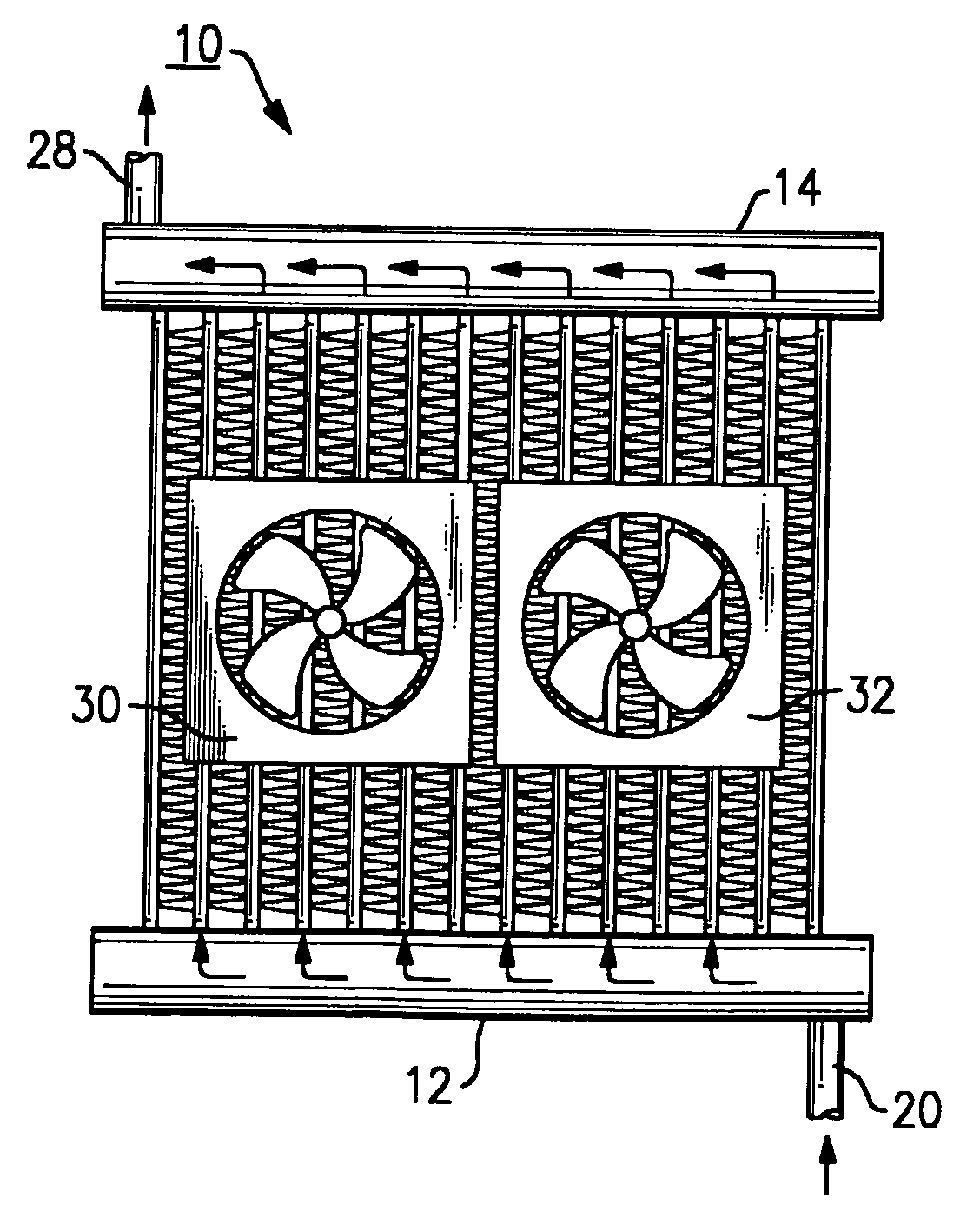
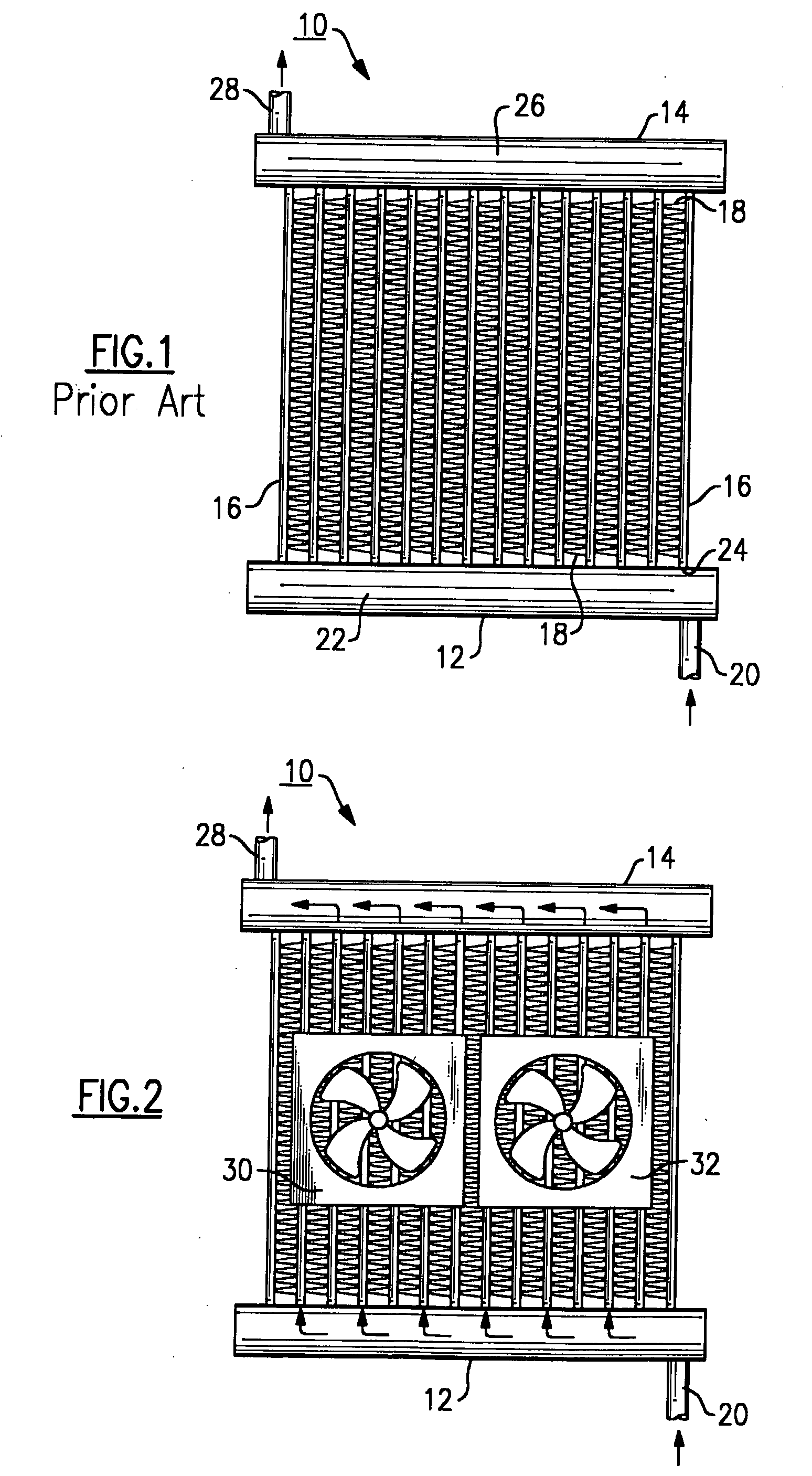
[0023]Referring to FIG. 1, a parallel flow (microchannel or minichannel) heat exchanger 10 is shown, as an example, to include an inlet header or manifold 12, an outlet header or manifold 14 and a plurality of parallel disposed channels 16 fluidly interconnecting the inlet manifold 12 to the outlet manifold 14. Generally, the inlet and outlet headers 12 and 14 are cylindrical in shape, and the channels 16 are tubes (or extrusions) of flattened or round cross-section. Channels 16 normally have a plurality of internal and external heat transfer enhancement elements, such as fins. For instance, external fins 18, uniformly disposed therebetween for the enhancement of the heat exchange process and structural rigidity are typically furnace-brazed. Channels 16 may have internal heat transfer enhancements and structural elements as well.

[0024]In operation, refrigerant flows into the inlet opening 20 and into the internal cavity 22 of the inlet header 12. From the internal cavity 22, the ref...


PUM


Abstract

A refrigerant system heat exchanger is characterized by improved airflow distribution through the use of at least one of the fans operating in the pulse width modulation or variable speed mode. Improved airflow distribution can be used to alleviate the effects of refrigerant maldistribution, enhance heat exchanger performance, prevent compressor flooding and improve comfort in the conditioned space.

Description

CROSS-REFERENCE TO RELATED APPLICATION[0001]Reference is made to and this application claims priority from and the benefit of U.S. Provisional Application Ser. No. 60 / 649,427, filed Feb. 2, 2005, and entitled PULSE WIDTH MODULATION OF FANS FOR PARALLEL FLOW HEAT EXCHANGERS, which application is incorporated herein in its entirety by reference.BACKGROUND OF THE INVENTION[0002]This invention relates generally to heat exchangers of air conditioning, heat pump and refrigeration systems and, more particularly, to parallel flow (minichannel or microchannel) evaporators thereof.[0003]A definition of a so-called parallel flow heat exchanger is widely used in the air conditioning and refrigeration industry and designates a heat exchanger with a plurality of parallel passages or channels typically of flattened or round cross-section, among which refrigerant is distributed and flown in the orientation generally substantially perpendicular to the refrigerant flow direction in the inlet and outl...

Claims


Application Information

Patent Timeline
Patent Type & Authority Applications(United States)
IPC IPC(8): G05D23/00
CPCF25B49/02F25B2600/112Y02B30/743F28F27/00F28D1/024Y02B30/70G05D23/00
Inventor LIFSON, ALEXANDERTARAS, MICHAEL F.
Owner CARRIER CORP
Why Eureka
Try Eureka