Vibration Based Injection Molding Machine Damage Detection and Health Monitoring

a damage detection technology, applied in the field of vibration-based injection molding machine damage detection and health monitoring, can solve the problems of fracture, bending, or other damage of injection molding machines, typically subjected to very high levels of cyclic stress, shock and vibration,

Inactive Publication Date: 2008-05-15
HUSKY INJECTION MOLDING SYST LTD
View PDF11 Cites 35 Cited by
  • Summary
  • Abstract
  • Description
  • Claims
  • Application Information

AI Technical Summary

Problems solved by technology

Injection molding machines such as, but not limited to, hot runner injection molding machine manufactured by Husky Injection Molding Systems Ltd., are typically subjected to very high levels of cyclic stress, shock, and vibration due to the nature of the injection molding process.
This cyclic loading, shock, and vibration of the components of the injection molding machine at high stress levels causes fatigue over time which, if undetected, can result in cracking, fracture, bending, or other damage within the injection molding machine.
In some cases, catastrophic system failure of the injection molding machine can occur.
The leakage of molten plastics or resin material outside of the designed melt path has many undesirable effects.
For example, the leaking plastic from a cracked manifold can fill a significant portion of the internal voids of the injection molding machine and damage or contaminate multiple components in the injection molding machine, such as, but not limited to, heaters, wires, terminals, insulation, as well as other parts or components.
The cost of spare parts, labor to clean, repair, and / or inspect the injection molding machine, and the loss of productivity of the injection molding machine during repair can be very high and unsatisfactory to the end users.
Lack of this knowledge in this regard, however, does not limit the capabilities of the system in terms of noticing changes, though it may make the determination of the exact cause of the change more difficult.

Method used


Image

  • Vibration Based Injection Molding Machine Damage Detection and Health Monitoring
  • Vibration Based Injection Molding Machine Damage Detection and Health Monitoring
  • Vibration Based Injection Molding Machine Damage Detection and Health Monitoring

Examples


Embodiment Construction

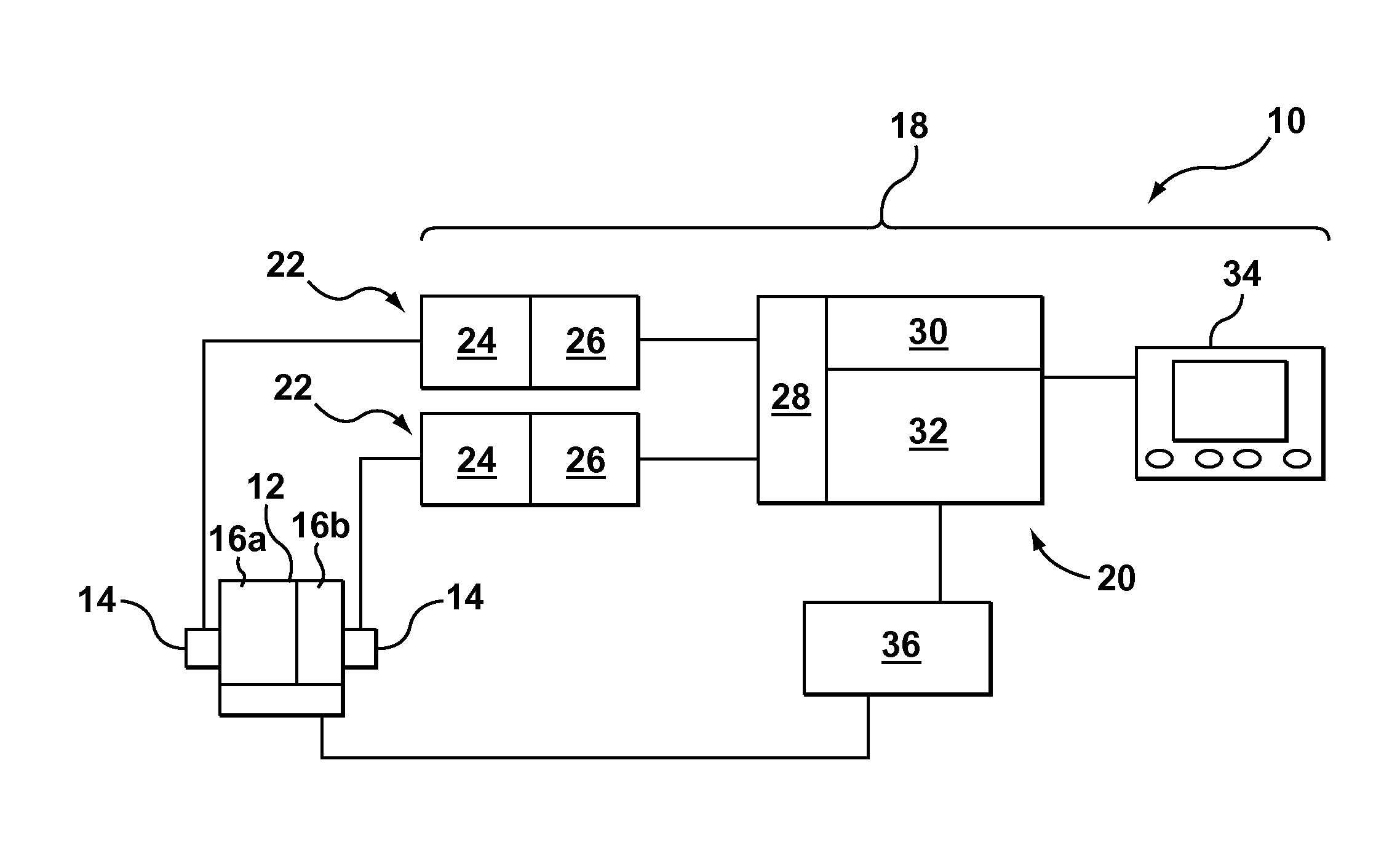
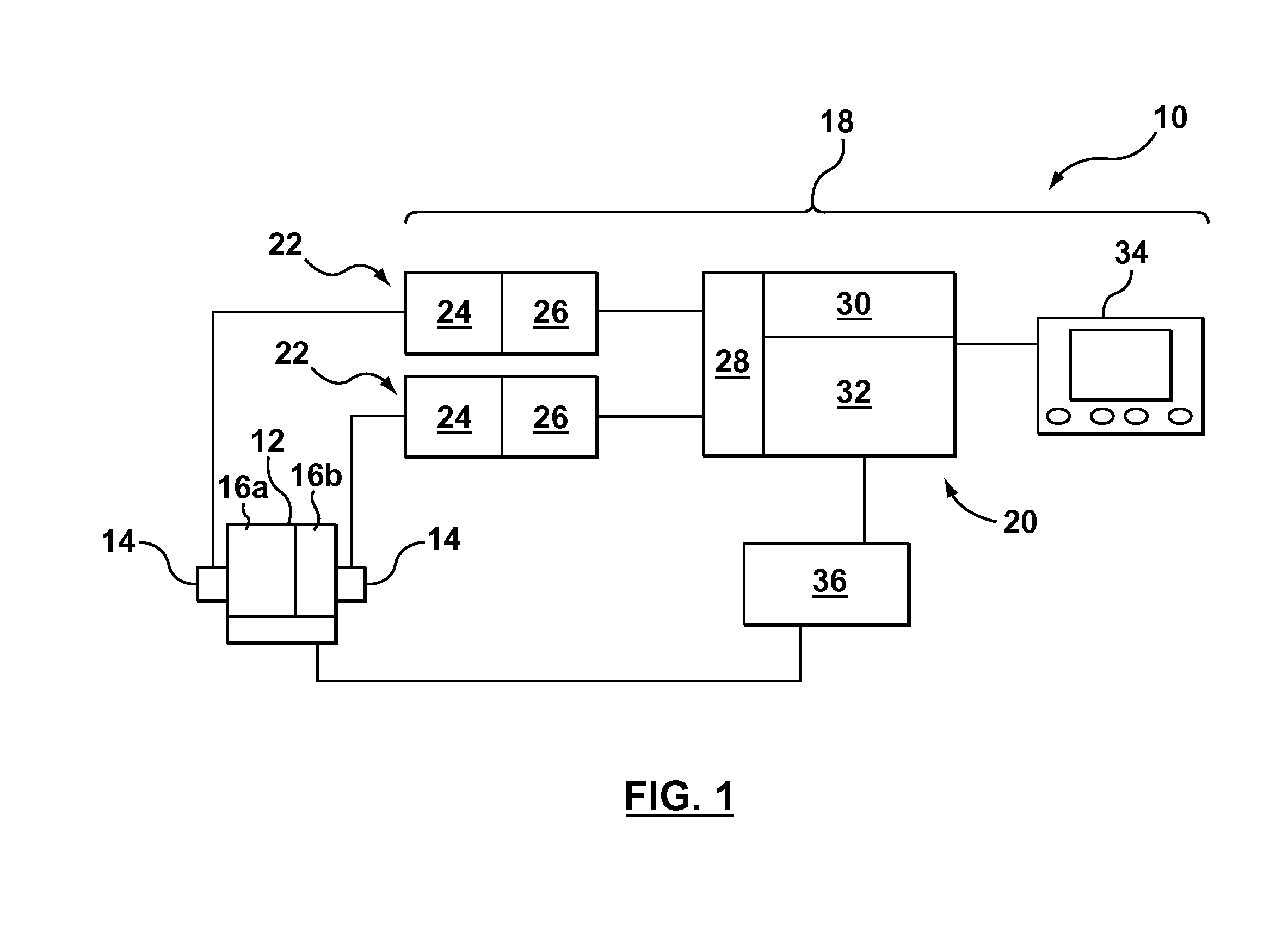
[0018]Referring to FIG. 1, one embodiment of a system 10 for detecting and / or monitoring the condition of an injection molding machine 12 according to the present disclosure is shown in schematic block diagram form. One or more sensors 14 may be operatively connected to one or more components 16a, 16b of the injection molding machine 12 to sense vibration, displacement, velocity, force, or acceleration of the components 16. The sensors 14 may include any sensor or transducer design known to those skilled in the art such as, but not limited to, accelerometers (e.g., a micro electro-mechanical system MEMS accelerometer, a quartz piezo-electric accelerometer, or the like), velocity transducers, displacement transducers, force transducers, or the like.

[0019]As will be explained in greater detail hereinbelow, the detection system 10 may monitor the natural frequencies or modes of vibration of one or more components 16a, 16b of the injection molding machine 12 to determine the condition o...


PUM

PropertyMeasurementUnit
frequencyaaaaaaaaaa
forceaaaaaaaaaa
velocityaaaaaaaaaa

Abstract

A system and method for evaluating the structural integrity of an injection molding machine and / or a component thereof may comprise at least one sensor operatively connected to a component of the injection molding machine. The sensor may transmit a signal representative of the movement of the injection molding machine. A processor may convert this signal into a frequency domain signal and compare it against a frequency template. Changes to the structural integrity of the injection molding machine may result in changes to the system's frequency response spectrum such as, but not limited to, amplification of certain frequency peaks, amplitude variations, changes in the damping characteristics, the shifting of the fundamental mode (i.e., the first natural frequency), shifting of higher order modes (those above the fundamental mode), or the introduction of a new frequency mode of vibration that did not exist prior to the damage of the component.

Description

TECHNICAL FIELD[0001]The present disclosure relates to molding systems and more particularly, relates to systems and methods for detecting damage of a component of an injection molding system.BACKGROUND INFORMATION[0002]Injection molding machines such as, but not limited to, hot runner injection molding machine manufactured by Husky Injection Molding Systems Ltd., are typically subjected to very high levels of cyclic stress, shock, and vibration due to the nature of the injection molding process. As the injection molding process continues to develop and evolve, future injection molding machines will likely utilize faster injection times, thinner wall components, new materials with poorly understood failure characteristics, and higher injection pressures. This cyclic loading, shock, and vibration of the components of the injection molding machine at high stress levels causes fatigue over time which, if undetected, can result in cracking, fracture, bending, or other damage within the ...

Claims


Application Information

Patent Timeline
Patent Type & Authority Applications(United States)
IPC IPC(8): B29C45/76
CPCB29C45/17B29C45/84B29C45/2725
Inventor ESSER, BRIAN
Owner HUSKY INJECTION MOLDING SYST LTD
Why Eureka
Try Eureka