
Circuit and method operable in functional and diagnostic modes

a functional and diagnostic mode technology, applied in the field of data processing systems, can solve the problems of difficult task of carefully balancing the clock, non-robust design, etc., and achieve the effect of simple us

Active Publication Date: 2008-05-15
ARM LTD
View PDF13 Cites 31 Cited by
  • Summary
  • Abstract
  • Description
  • Claims
  • Application Information

AI Technical Summary

Benefits of technology

[0014]Although it is not a strict requirement that the scan clock and functional clock are non-overlapping it is advantageous to make them so. Clocks that overlap could result in a non-robust design with the difficult task of carefully balancing the clocks. Therefore, the non-overlapped approach is highly desirable as it ensures that the internal race condition of the flop is met and also greatly reduces any possibility of an external race condition even with large amounts of skew between the two clocks. Furthermore, as will become clear from the specific description there are several logically quite simple ways to produce such clocks.
[0019]An effective yet simple way of ensuring, both that the scanned input is isolated during the functional mode of operation and that the slave latch receives data from the scan input clocked by the scan clock during the scan mode of operation is to provide a tristatable device on the scan input with the scan clock as its control clock. Doing this, provides the required functionality of the system in a simple yet highly effective manner.
[0021]One way of enabling the master latch to be clocked by the functional clock in functional mode and yet not be clocked by it in scan mode is to provide a master latch functional clock signal which is made inactive in scan mode.
[0033]If the predetermined clock signal values are chosen appropriately, the flip flops can provide a low impedance path from the scan input to the scan output, such that a value provided at the scan input of a first flip flop will ripple through the flip flops and be stored in all of the latches. This property of the circuit allows for flush through mode of operation and provides a convenient way of setting a known value in the latches at reset. This is a highly valuable tool.
[0039]It may be desirable to store a particular value in one latch and a different value in another. This can be achieved by the simple use of inverters between the flops.

Problems solved by technology

Clocks that overlap could result in a non-robust design with the difficult task of carefully balancing the clocks.

Method used


Image

  • Circuit and method operable in functional and diagnostic modes
  • Circuit and method operable in functional and diagnostic modes
  • Circuit and method operable in functional and diagnostic modes

Examples


Embodiment Construction

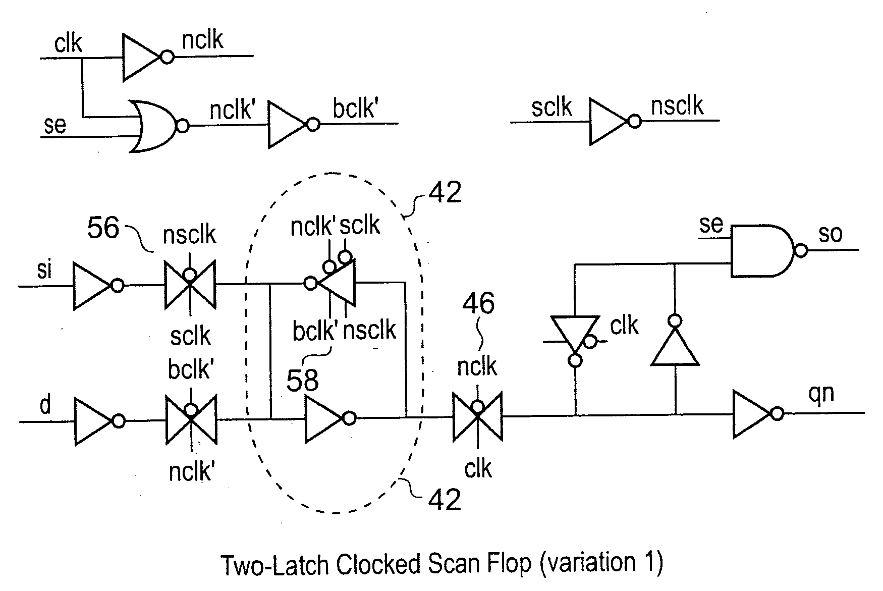
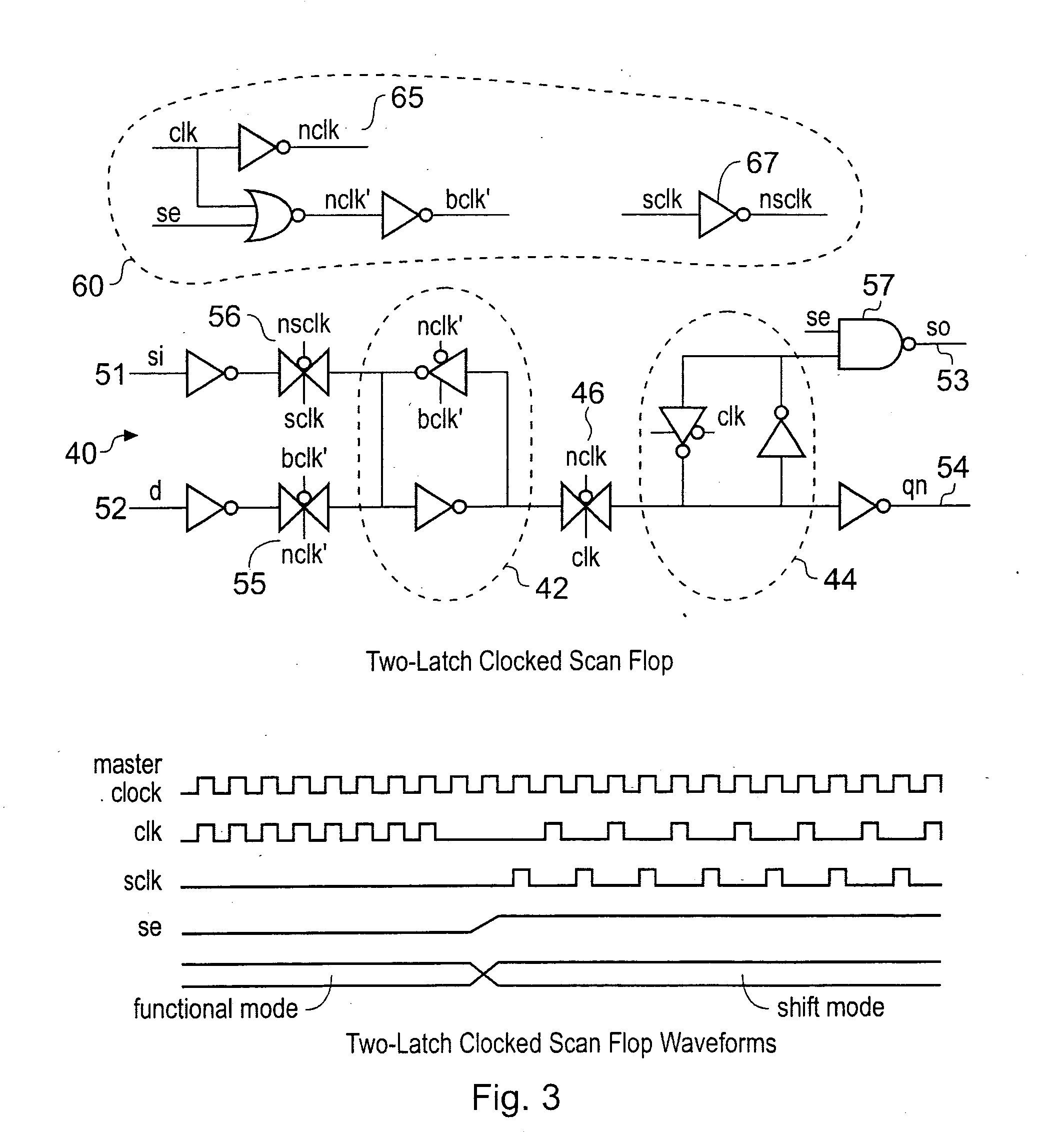
[0052]FIG. 3 shows a two latch clocked scan flop 40 according to an embodiment of the present invention. Two latch clocked scan flop 40 comprises a master latch 42 and a slave latch 44. These are separated by a transmission gate 46.

[0053]The Figure also shows clock generation logic 60 comprising logic 65 operable to generate functional clock signals and logic 67 operable to generate scan clock signals. A waveform diagram demonstrating these clock signals and how the flop functions is also shown.

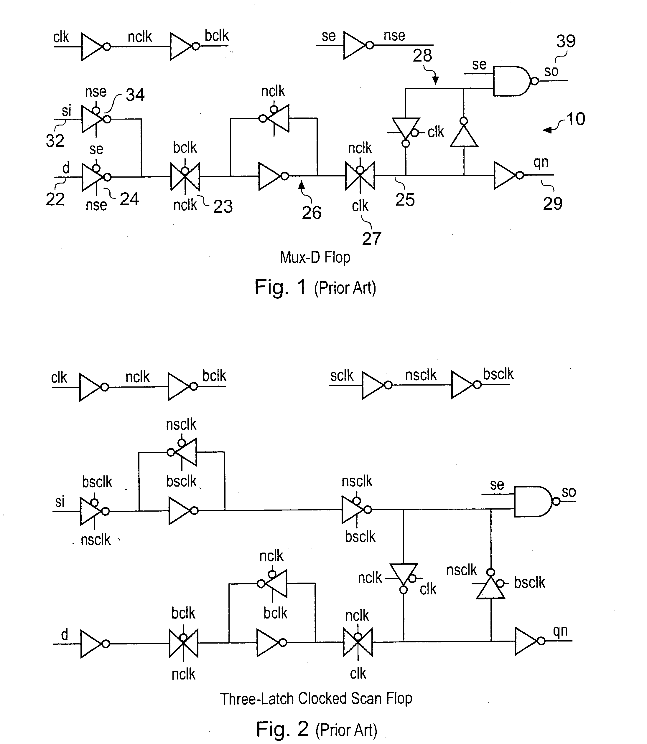
[0054]As can be appreciated, there are 38 transistors in this implementation which makes it approximately 5% larger than that mux-D approach. There is also one additional clock signal the scan clock signal.

[0055]During functional operation the scan enable signal and the scan clock input are held low. Functional clock generation logic 65 provides active clock signals including nclk′ and bclk′. In this mode the two latch scan flop 40 functions a a traditional master slave flip flop.

[0056]When d...


PUM


Abstract

The application discloses a circuit comprising at least one flip flop, said flip flop comprising: a master latch and a slave latch; a data signal input and a scan signal input arranged in parallel to each other and each input comprising a tristateable device; and a scan enable signal input, a functional clock signal input and a scan clock signal input; wherein: in response to a first predetermined value of said scan enable signal indicating a functional mode of operation, said scan input tristateable device is operable to isolate said scan input from said master latch, and said master latch is operable in response to said functional clock to receive data from said data input and to output data to said slave latch and said slave latch is operable in response to said functional clock to receive data from said master latch and to output data at said data output; and in response to a second predetermined value of said scan enable signal indicating a scan mode of operation said data input tristateable device is operable to isolate said data input from said master latch, and said master latch is operable in response to said scan clock to receive data from said scan input and said slave latch is operable in response to said functional clock to receive data from said master latch and to output data at said scan output.

Description

BACKGROUND OF THE INVENTION[0001]1. Field of the Invention[0002]This invention relates to the field of data processing systems. More particularly, this invention relates to the field of diagnostic testing of circuits.[0003]2. Description of the Prior Art[0004]In order to test integrated circuits effectively it is known to provide diagnostic features on the circuit such as scan cells. Scan cells allow scan testing of the circuit to be performed which allows for the control and observation of state elements within the integrated circuit. Scan cells are generally provided in association with flip-flops or latches on the circuit by adding a scan cell capability to the design whereby a signal value may be captured and then serially scanned out of the circuit for diagnostic purposes.[0005]Providing flip flops with a scan cell capability can be done in a number of ways. A common way is to provide a multiplexed flip-flop, which has a multiplexer on its input and output which can select betw...

Claims


Application Information

Patent Timeline
IPC IPC(8): G01R31/28
CPCG01R31/318552G01R31/318541
Inventor FREDERICK, MARLIN
Owner ARM LTD
Learn More