
Exhaust Heat Recovery System Abnormality Detection Device

a technology of exhaust heat recovery and abnormal detection, which is applied in the direction of instruments, heat measurement, lighting and heating apparatus, etc., can solve the problems of abnormality of switching valve and abnormality of exhaust gas path, and achieve the effect of preventing erroneous decisions and high precision

Inactive Publication Date: 2008-05-22
TOYOTA JIDOSHA KK
View PDF9 Cites 36 Cited by
  • Summary
  • Abstract
  • Description
  • Claims
  • Application Information

AI Technical Summary

Benefits of technology

[0026]In accordance with the present invention the quantity of heat recovered is calculated from an amount of air aspirated by the engine, an amount of fuel injected, the engine's rate of rotation, and the medium's temperature. In other words, the quantity of heat recovered is calculated depending on the engine's load state. Thus a quantity of heat recovered depending on the engine's state can be calculated with high precision, and whether the switching valve has abnormality can be detected with high precision.
[0036]In accordance with the present invention the determinator determines whether the switching valve has abnormality at a temporal point different than when the second abnormality determinator determines whether the open and close valve has abnormality. Determining at a temporal point whether the open and close valve has abnormality and determining at a different temporal point whether the switching valve has abnormality, can provide a decision on abnormality with high precision. Erroneous decision on the open and close valve or the switching valve can be prevented.
[0038]In accordance with the present invention the determinator determines whether the switching valve has abnormality after the second abnormality determinator determines whether the open and close valve has abnormality. More specifically, when the second decision making temperature is detected and it is smaller than the second temperature corresponding to a period elapsing before the second decision making temperature is attained, the second abnormality determiner determined that the open and close valve has abnormality, and when the first decision making temperature is detected and it is smaller than the first temperature corresponding to a period elapsing before the first decision making temperature is attained, a decision is made that the switching valve has abnormality. Determining at a temporal point whether the open and close valve has abnormality and determining at a different temporal point whether the switching valve has abnormality, can prevent erroneous decision and provide a decision on abnormality with high precision.

Problems solved by technology

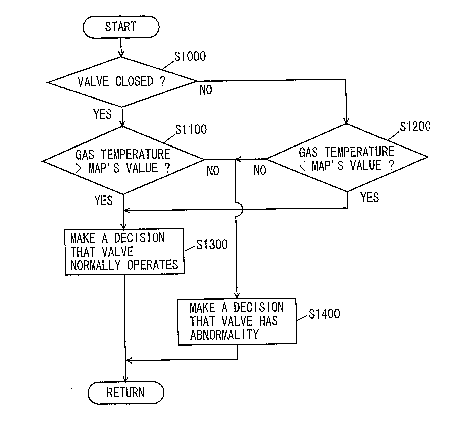
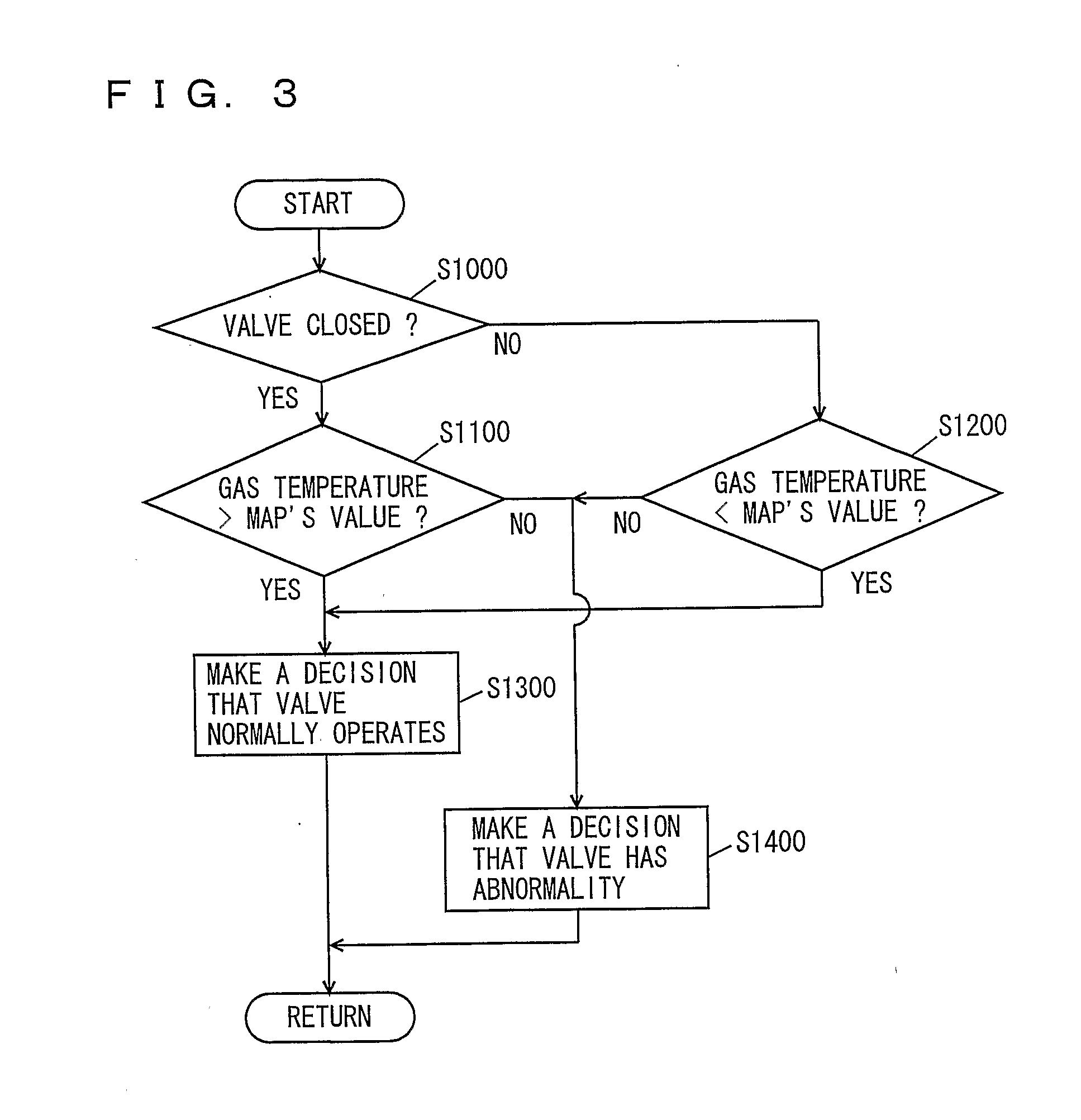
As such, when the switching valve is switched to pass exhaust gas through the bypass and the gas temperature detector nonetheless detects that the exhaust gas's temperature (variation in temperature) is low, a decision can be made that the bypass is not passing the exhaust gas and hence the switching valve has abnormality.
Thus the exhaust heat recovery system's abnormality detection device can detect that the exhaust gas path switching valve has abnormality.

Method used


Image

  • Exhaust Heat Recovery System Abnormality Detection Device
  • Exhaust Heat Recovery System Abnormality Detection Device
  • Exhaust Heat Recovery System Abnormality Detection Device

Examples


first embodiment

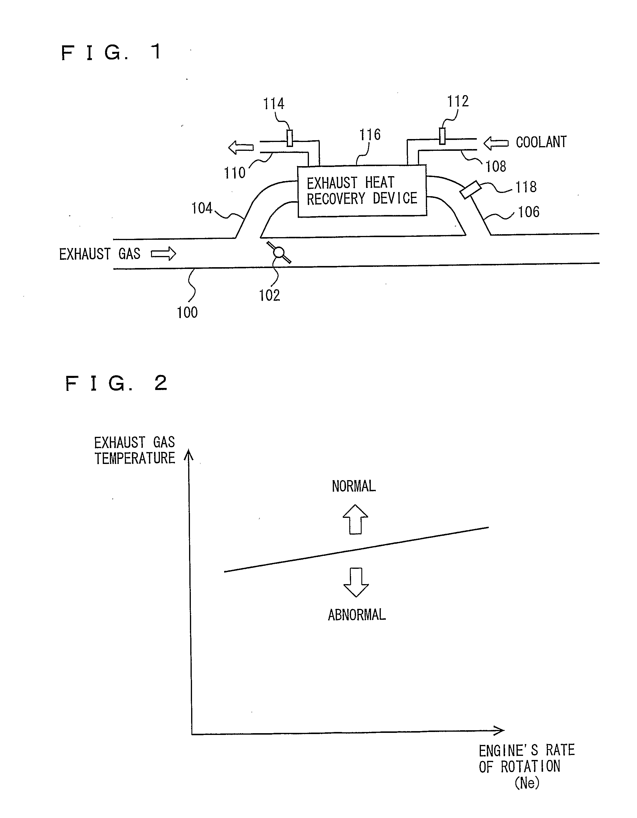
[0053]As shown in FIG. 1, the present embodiment provides an exhaust heat recovery system including bypasses 140, 160 connected parallel to an exhaust pipe 100 passing exhaust gas therethrough, an exhaust heat recovery device 116 disposed between bypasses 104 and 106, a switching valve 102 disposed in exhaust pipe 100, and a gas temperature sensor 118 disposed at bypass 106.

[0054]Exhaust pipe 100 passes exhaust gas exhausted from an engine. The exhaust gas passes through a ternary catalyst converter (not shown) and a muffler (also not shown) and is subsequently exhausted outside the vehicle. Exhaust pipe 100 is provided with switching valve 102 at a location downstream of a branch to bypass 104 and upstream of a confluence with bypass 106. When switching valve 102 is closed, switching valve 102 closes the path, and exhaust gas passing through exhaust pipe 100 passes through bypass 104. After it has passed through exhaust heat recovery device 116, the exhaust gas passes through bypas...

second embodiment

[0077]A second embodiment provides an exhaust heat recovery system's abnormality detection device as described hereinafter.

[0078]The present embodiment provides an exhaust heat recovery system's abnormality detection device different from that of the first embodiment in that the ECU executes a program having a different structure for control. Except that, it is configured to be identical to that of the first embodiment and accordingly, labeled identically and also identical in function.

[0079]With reference to FIG. 4, the present exhaust heat recovery system's abnormality detection device, or an ECU, executes a program having a structure for control, as described hereinafter.

[0080]Note that in the FIG. 4 flow chart any step identical to that indicated in the FIG. 3 flow chart is identically labeled.

[0081]At S1500 the ECU determines whether temperature A detected by upstream temperature sensor 112 is smaller than temperature B detected by downstream temperature sensor 114. If so (YES ...

third embodiment

[0088]A third embodiment provides an exhaust heat recovery system's abnormality detection device as will be described hereinafter.

[0089]The present embodiment provides the exhaust heat recovery system's abnormality detection device different from that of the first embodiment in that, as shown in FIG. 5, upstream path 108 is not provided with upstream temperature sensor 112 and that bypass 106 is not provided with gas temperature sensor 118 and bypass 104 is instead provided with a gas temperature sensor 120. Except that, it is configured to be identical to that of the first embodiment and accordingly, labeled identically and also identical in function.

[0090]Gas temperature sensor 120 detects exhaust gas's temperature in bypass 104 and transmits to an ECU a detection signal corresponding to the exhaust gas's temperature as detected.

[0091]Furthermore in the present embodiment an engine is provided with a thermostat (not shown) introducing a medium (or coolant) from the engine to a rad...


PUM


Abstract

An ECU executes a program including the steps of: when a switching valve is controlled to be closed, comparing exhaust gas's temperature, as detected, with a map value; if the exhaust gas's temperature is larger than the map value, determining that the switching valve normally operates; and if the exhaust gas's temperature is smaller than the map value, determining that the switching valve has abnormality.

Description

TECHNICAL FIELD[0001]The present invention relates generally to exhaust heat recovery system abnormality detection devices and particularly to abnormality detection devices detecting whether an exhaust gas path switching valve has abnormality.BACKGROUND ART[0002]Conventionally, thermal energy of exhaust gas exhausted from automobile engines has been recovered by employing techniques. For example, there has been proposed an exhaust heat recovery system attaching an exhaust heat recovery device (e.g., a heat exchanger) to an automobile's exhaust heat system to absorb thermal energy of exhaust gas to use the absorbed thermal energy for heating, a water heater, and the like. In The thus configured exhaust heat recovery system if the exhaust heat recovery device has abnormality the abnormality must be detected as early as possible in order to prevent secondary abnormality attributed to the exhaust heat recovery device. For example, Japanese Utility Model Laying-Open No. 61-58502 disclose...

Claims


Application Information

Patent Timeline
Patent Type & Authority Applications(United States)
IPC IPC(8): G01M15/00F01N3/00F01N7/00F02G5/02F01N5/02F24H1/00
CPCF01N5/02F01N11/002F01N2240/02Y02T10/47F02G5/02Y02T10/16Y02T10/166F01N2550/06Y02T10/12Y02T10/40
Inventor HARADA, OSAMUSASAKI, TOSHITAKE
Owner TOYOTA JIDOSHA KK
Learn More