Cooling system and method

a cooling system and cooling fluid technology, applied in the direction of cooling fluid circulation, domestic cooling apparatus, lighting and heating apparatus, etc., can solve the problems of heat transfer from the refrigerant to the cooler surroundings, many buildings also require mechanical cooling, energy-intensive mechanical cooling systems must be operated, etc., and achieve the effect of substantial energy savings

Active Publication Date: 2008-05-22
BAILEY PETER F +2
View PDF5 Cites 46 Cited by
  • Summary
  • Abstract
  • Description
  • Claims
  • Application Information

AI Technical Summary

Benefits of technology

[0007]A preferred embodiment of the system and method of the present invention provides for an extremely efficient hybrid mechanical cooling or “free” cooling, air conditioning system. The cooling system disclosed permits the floating of head pr...

Problems solved by technology

This results in heat transfer from the refrigerant to cooler surroundings.
However, many buildings also require mechanical cooling during the winter months as well.
This is due to high internal heat loads that are generated by processes, persons, lighting, computers and other office equipment situated within the building.
If the building has no means to bring in outside air to cool the building, then energy intensive mechani...

Method used


Image

  • Cooling system and method
  • Cooling system and method
  • Cooling system and method

Examples


Embodiment Construction

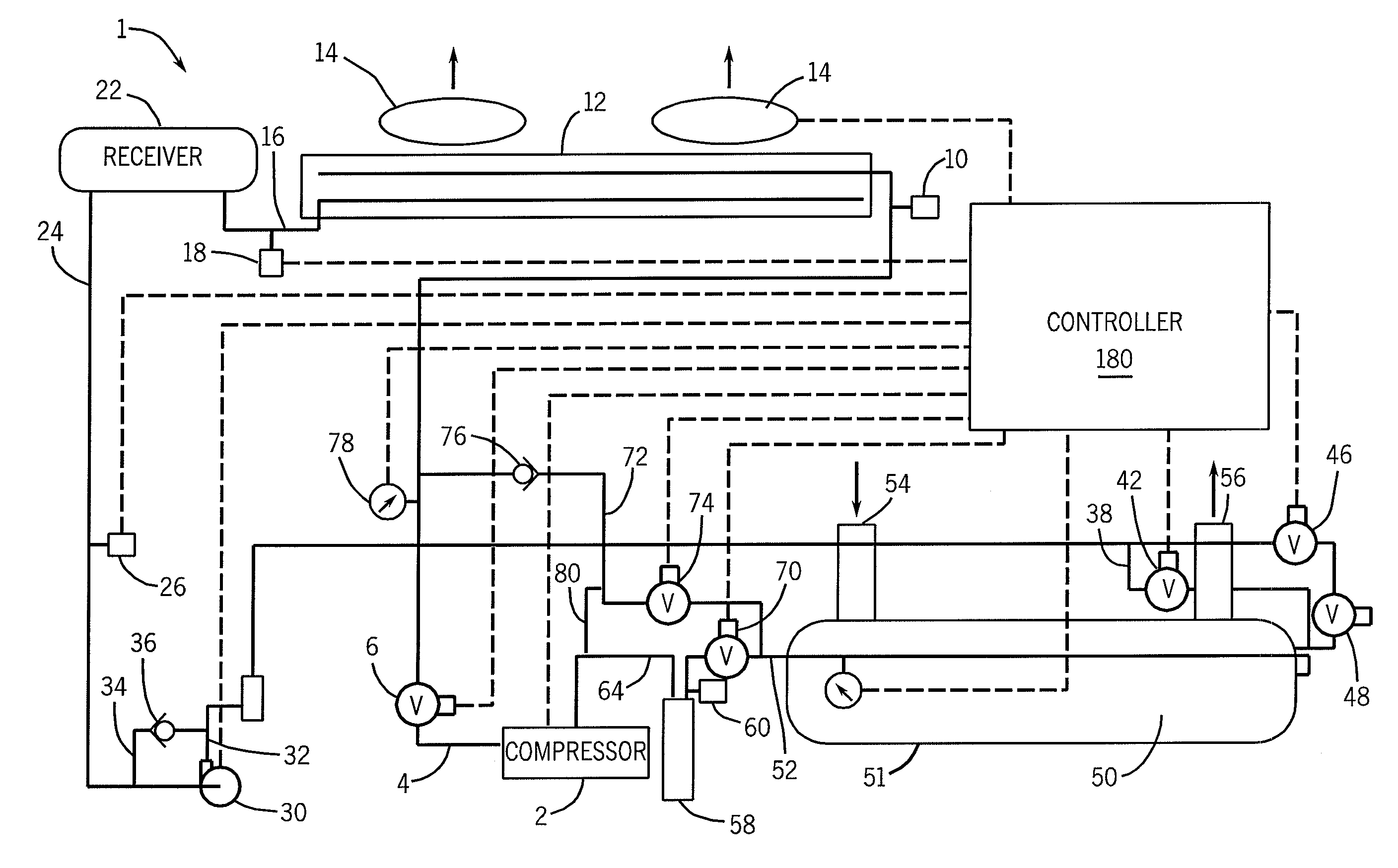
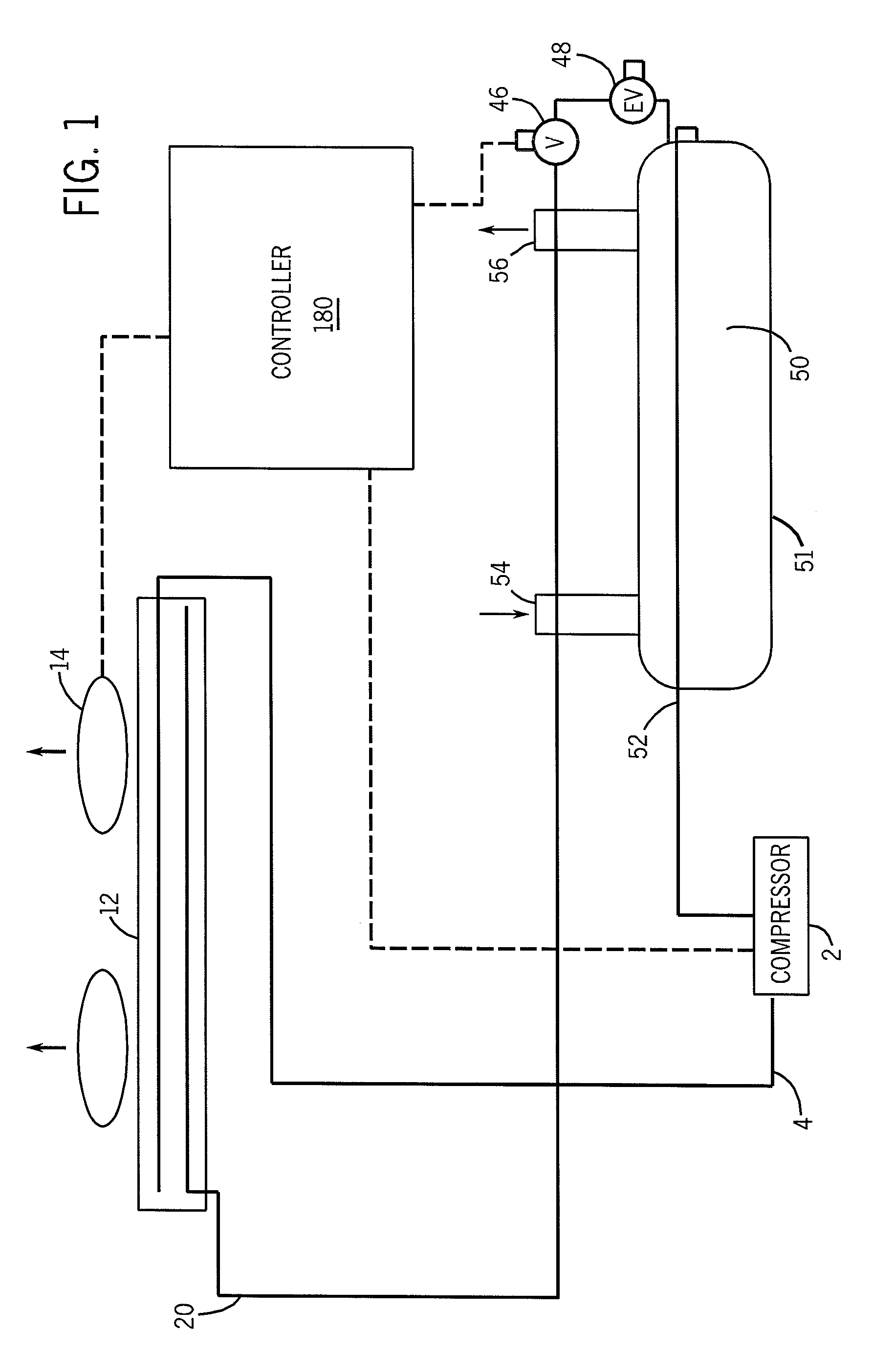
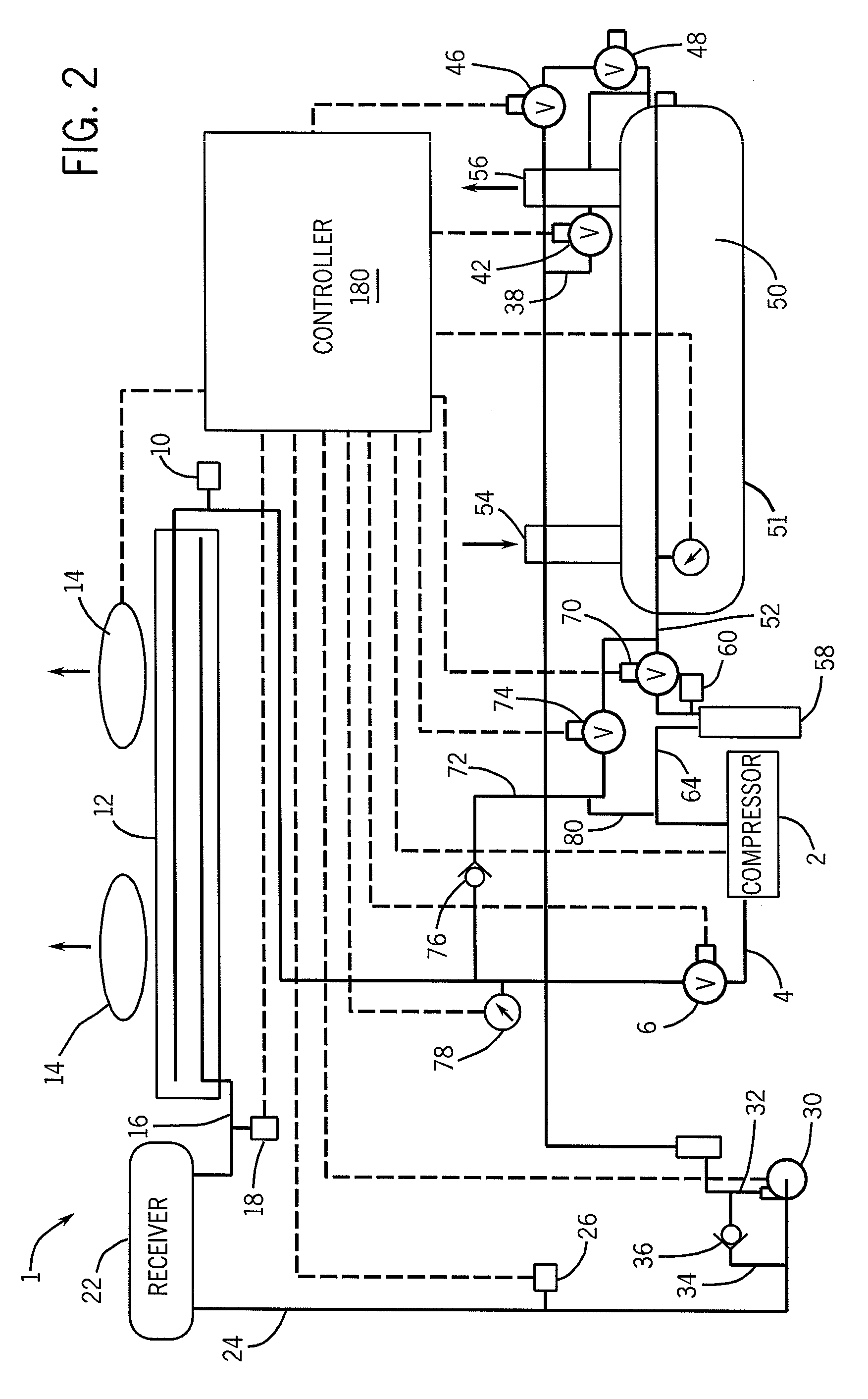
[0022]Referring now to FIG. 1 there is illustrated a prior art cooling system that circulates refrigerant throughout. The refrigerant may be any suitable vaporizable refrigerant. The cooling system 1 of FIG. 1 is comprised of a compressor 2. The compressor 2 compresses the refrigerant from a warm vapor state to a hot, highly pressurized state. The refrigerant is discharged along the compressor / condenser line 4. The refrigerant moves to the condenser 12, which is normally located outdoors. The condenser 12 is a heat exchanger within which the refrigerant is allowed to condense to a liquid. Condenser fans 14 are then used to draw heat away from the condenser 12. The liquid refrigerant exits the condenser 12 via the condenser / expansion device line 20, and flows through an expansion device 48 to the evaporator 50. Water, or some other suitable liquid, is circulated through the chiller barrel 51 via the chilled water return pipe 54 and the chilled water supply pipe 56. The liquid refrige...


PUM


Abstract

The present invention related to cooling systems. More specifically, the present invention relates to a system for cooling one or more parts of a building and or processes comprising a compressor, a condenser having an inlet and an outlet and a plurality of condenser cooling fans, a receiver, a liquid refrigerant pump, an expansion device, an evaporator, the evaporator being surrounded by a chiller barrel having a cooled water return and a chilled water supply line, and refrigerant line means interconnecting the compressor, condenser, expansion device and evaporator in series, in a closed loop for circulating refrigerant therethrough; means for switching the cooling system between free cooling and mechanical cooling and means for actively floating the head pressure in both mechanical and free cooling modes.

Description

FIELD OF THE INVENTION[0001]The present invention relates generally to cooling systems and methods. More specifically, the present invention relates to a system and method for the active and passive cooling of buildings or certain processes that are located in cooler climates with high heat loads.BACKGROUND OF THE INVENTION[0002]Vapor compression refrigeration systems are well known in the art. Vapor compression systems circulate refrigerant to achieve a desired cooling effect. Starting with the evaporator, which is where the desired cooling effect is achieved, refrigerant evaporates, thereby carrying away the latent heat of vaporization, as it passes through the evaporator. The evaporator serves as a heat exchanger. Air, water, glycol or other cooling mediums, which are hereinafter referred to interchangeably as “water” or “secondary fluids,” forced over the surface of the evaporator are cooled. At the same time, the evaporator surface is warmed, thereby continuing the vaporization...

Claims


Application Information

Patent Timeline
IPC IPC(8): F25B39/04F25B41/00F25D17/00
CPCF25B25/00F25B41/00F25B2400/0401F25B2400/0411F25B2400/16F25B2500/222Y02B30/743F25B2600/111F25B2600/2501F25B2700/04F25B2700/1931F25B2700/21162F25B2700/21163F25B2500/31Y02B30/70Y10S62/22
Inventor BAILEY, PETER F.JONCAS, WALTER C.DODGE, GREGORY W.
Owner BAILEY PETER F
Why Eureka
Try Eureka