Method For The Preferential Polishing Of Silicon Nitride Versus Silicon Oxide

a technology of silicon nitride and polishing method, which is applied in the direction of decorative surface effects, chemistry apparatus and processes, and other chemical processes, can solve the problems of achieving a higher suppressing silicon dioxide removal rate, so as to enhance suppress the and enhance the effect of silicon nitride removal ra

Inactive Publication Date: 2008-05-22
CLARKSON UNIVERSITY +1
View PDF19 Cites 13 Cited by
  • Summary
  • Abstract
  • Description
  • Claims
  • Application Information

AI Technical Summary

Benefits of technology

[0008]In the case of silicon nitride film polish rates, it is interesting to note that even though lysine adsorbs to both the silica abrasives and the silicon nitride film at pH 9, the silicon nitride removal rate is enhanced. This is in contrast to observations in our previous work where lysine when used with ceria (CeO2) abrasives at pH 9 suppressed the silicon nitride removal rate, W. G. America and S. V. Babu, Electrochemical and Solid State Letters, 7 (12) G327-G330 (2004). This highlights the importance ...

Problems solved by technology

Suppressing the silicon dioxide removal rate while at the same time achieving a higher silicon nitride removal rate is immensely challenging because the removal of silicon n...

Method used


Image

  • Method For The Preferential Polishing Of Silicon Nitride Versus Silicon Oxide
  • Method For The Preferential Polishing Of Silicon Nitride Versus Silicon Oxide

Examples


example 1

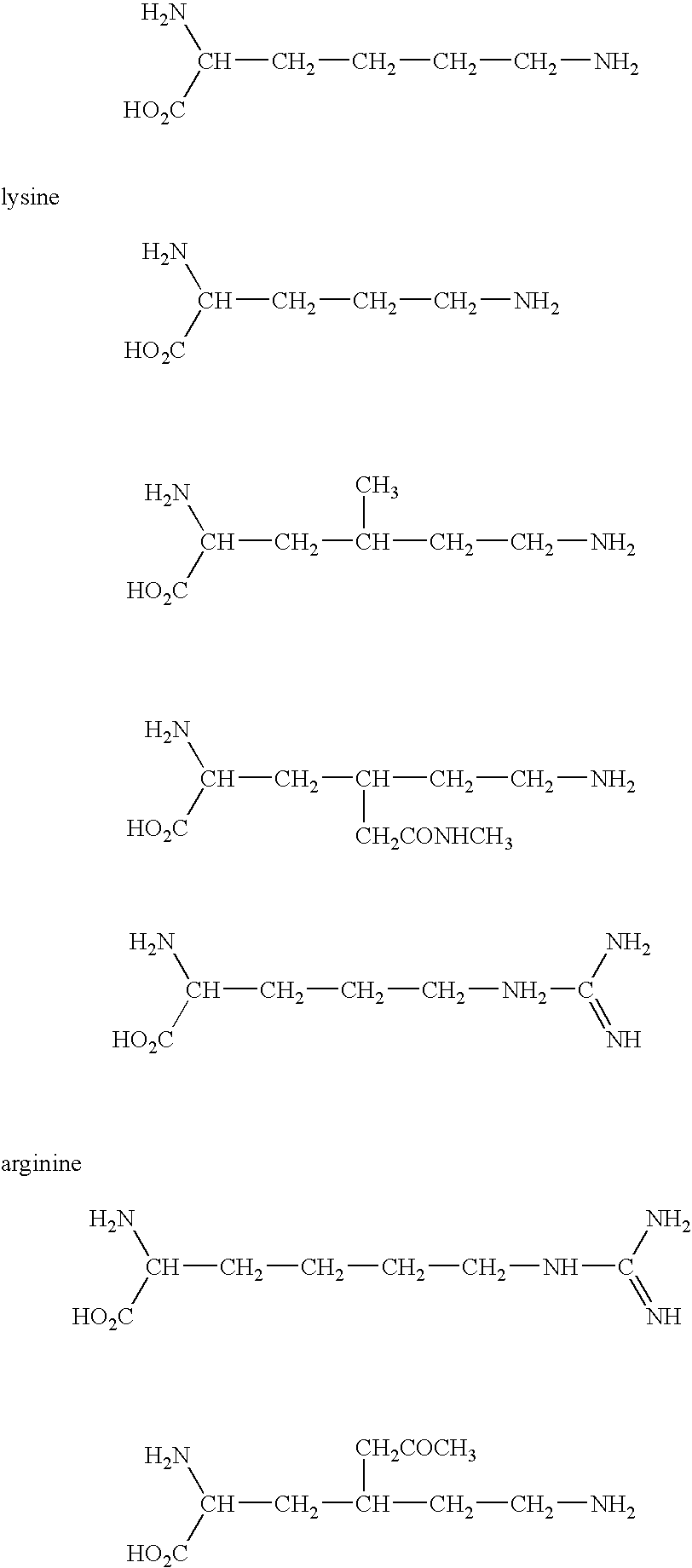
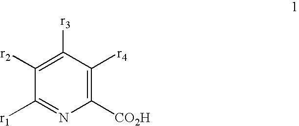
[0026]Six CMP slurries were separately prepared by dispersing 10% by weight of colloidal silica particles having a mean size of about 50 nm in water. The additives listed in Table 1 below in weight percent were added to the respective CMP slurries (where “Lys” means lysine; “Arg” means arginine; “LysHCl” means lysine mono hydrochloride; and “Pico” means picolinic acid). The pH of the CMP slurries was adjusted as shown in Table 1 below by adding a sufficient amount of potassium hydroxide.

[0027]The CMP slurries were then separately used to polish blanket silicon dioxide and silicon nitride films for one minute using a Westech-372 polisher using a down force as shown in Table 1, a carrier / platen speed of 75 / 75 rpm, a slurry flow rate of 200 ml / min and an IC-1400, k-groove polishing pad. The polishing pad was conditioned for one minute before every polishing experiment. The removal rates of reported in Table 1 are an average of the removal rates of two wafers each of silicon dioxide and...

example 2

[0029]Four CMP slurries were separately prepared by dispersing 10% by weight of colloidal silica particles having a mean size of about 50 nm in water. The additives listed in Table 2 below in weight percent were added to the respective CMP slurries (where “Arg” means arginine; “LysHCl” means lysine mono hydrochloride; and “Pico” means picolinic acid). The pH of the CMP slurries was adjusted as shown in Table 2 below by adding a sufficient amount of potassium hydroxide.

[0030]The CMP slurries were then separately used to polish blanket silicon dioxide and silicon nitride films for one minute using a Westech-372 polisher using a down force as shown in Table 2, a carrier / platen speed of 75 / 75 rpm, a slurry flow rate of 200 ml / min and an IC-1400, k-groove polishing pad. The polishing pad was conditioned for one minute before every polishing experiment. The removal rates of reported in Table 2 are an average of the removal rates of two wafers each of silicon dioxide and silicon nitride.

TA...


PUM

PropertyMeasurementUnit
Fractionaaaaaaaaaa
Fractionaaaaaaaaaa
Percent by massaaaaaaaaaa

Abstract

The present invention provides a method of removing silicon nitride in preference to silicon dioxide by CMP. The method utilizes a polishing slurry that includes colloidal silica abrasive particles dispersed in water and an additive that suppresses the silicon dioxide removal rate but enhances the silicon nitride removal rate. In one embodiment of the invention, the additive is lysine, which is effective at a pH of about 9, or arginine, which is effective at a pH of about 8. In another embodiment of the invention, the additive is lysine mono hydrochloride in combination with picolinic acid, which is effective at a pH of about 8, or arginine in combination with picolinic acid, which is effective at a pH of about 9.

Description

[0001]The U.S. Government has a paid-up license in this invention and the right in limited circumstances to require the patent owner to license others on reasonable terms as provided for by the terms of Grant No. NAG3-2744 awarded by NASA. The Government has certain rights in the invention.BACKGROUND OF THE INVENTION[0002]1. Field of Invention[0003]The present invention relates to compositions and methods for selectively removing silicon nitride in preference to silicon dioxide is by chemical-mechanical polishing.[0004]2. Description of Related Art[0005]Silicon nitride has been widely used as a barrier layer and / or as an etch stop layer to protect underlying devices from being removed during chemical-mechanical polishing (CMP) in integrated circuit (IC) fabrication. Accordingly, most CMP polishing slurries and processes have attempted to minimize the silicon nitride removal rate while attaining relatively high removal rates for other layers. CMP polishing slurries and processes that...

Claims


Application Information

Patent Timeline
IPC IPC(8): C03C15/00
CPCC09K3/1463C03C19/00
Inventor BABU, SURYADEVARA V.NATARAJAN, ANITA
Owner CLARKSON UNIVERSITY
Why Eureka
Try Eureka