
Method and system for improving particle beam lithography

a particle beam and particle technology, applied in the field of particle beam lithography, can solve the problems of high cost of mask sets, time-consuming and labor-intensive to produce mask sets, and requiring about a month turnaround time for creation, validation and repair

Inactive Publication Date: 2008-05-22
CADENCE DESIGN SYST INC
View PDF20 Cites 52 Cited by
  • Summary
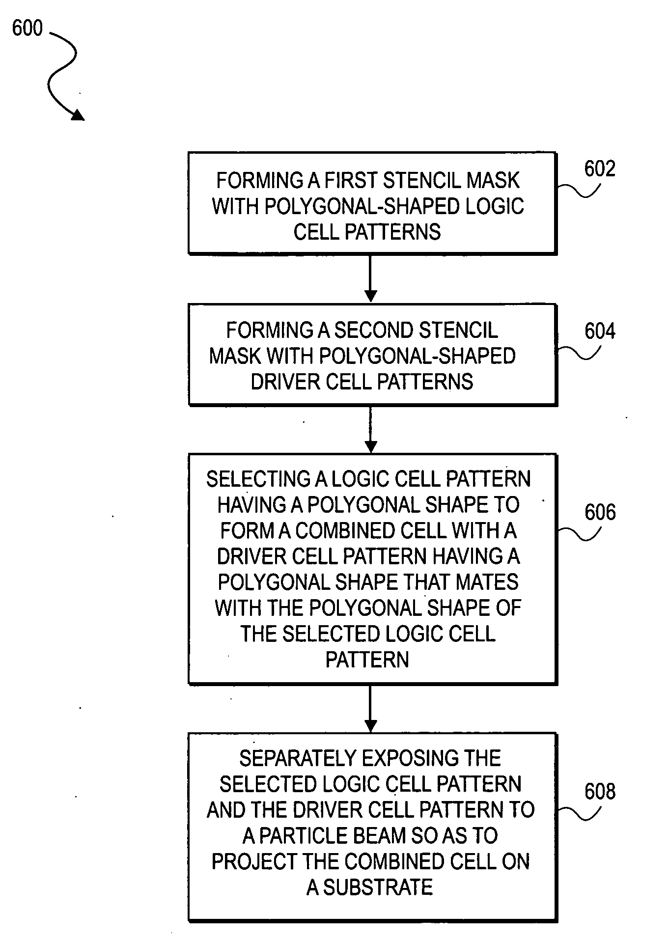
  • Abstract
  • Description
  • Claims
  • Application Information

AI Technical Summary

Benefits of technology

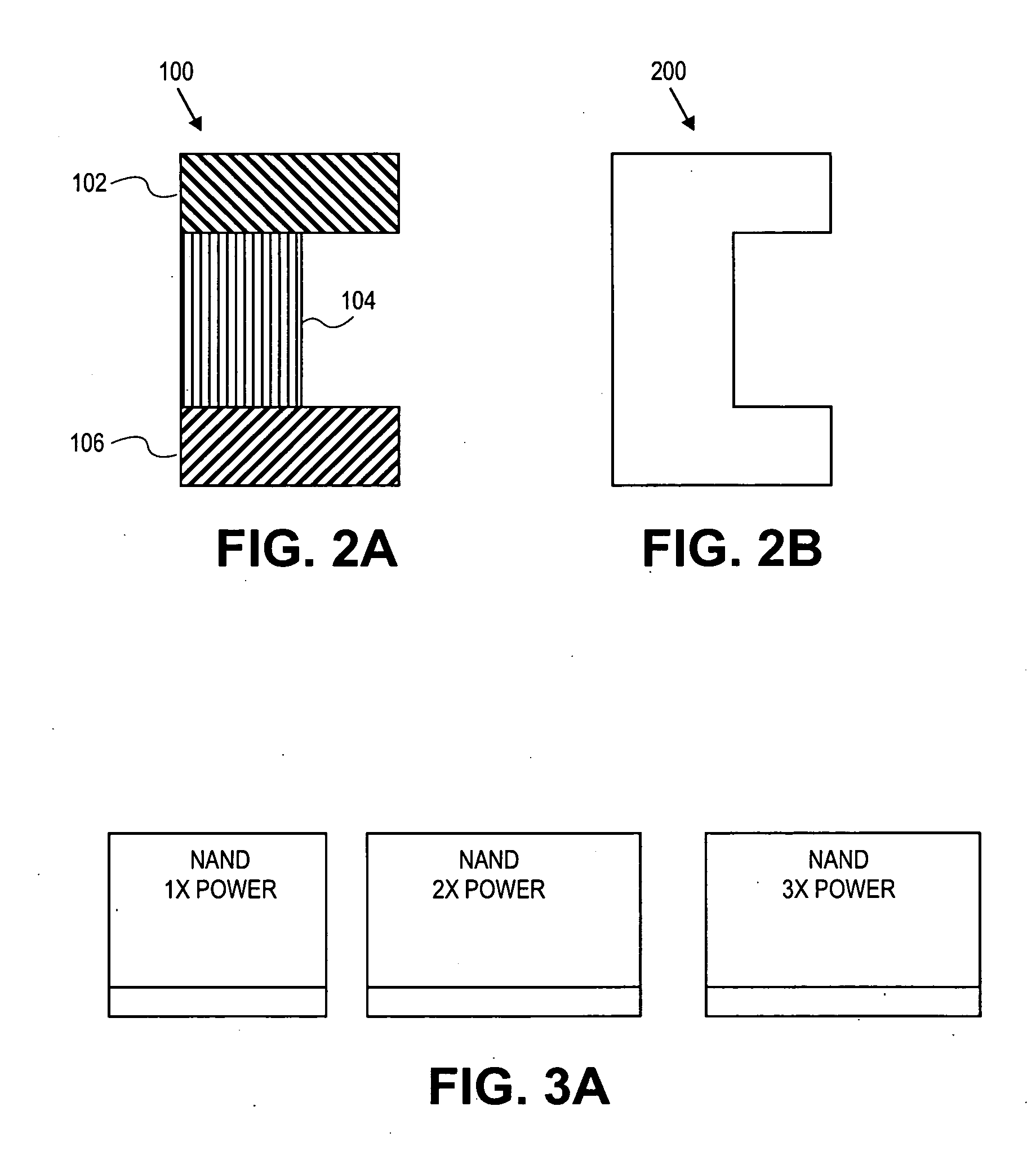
[0007]In one embodiment, the invention discloses a method for particle beam lithography including forming a plurality of cell patterns on a stencil mask and shaping at least one or more of the cell patterns with a polygonal-shaped contour. The method includes exposing a first polygonal-shaped cell pattern to a particle beam so as to project the first polygonal-shaped cell pattern on a substrate, and exposing a second polygonal-shaped cell pattern, having a contour that mates with the contour of the first polygonal-shaped cell pattern, to the particle beam so as to project the second polygonal-shaped cell pattern adjacent to the first polygonal-shaped cell pattern to thereby form a combined cell with the contour of the first polygonal-shaped cell pattern mated to the contour of the second polygonal-shaped cell pattern.

Problems solved by technology

The mask set is highly expensive, costing about 2 million dollars for a 90 nm design, and about 3 million dollars for a 65 nm design in the initial year of production.
Further, it is time-consuming to produce the mask sets, requiring about a month turnaround time for creation, validation and repair.
In addition, mask use is troublesome, since the use of light reaches physical limitations that have to be accounted for in some manner as the device sizes decrease, i.e., light becomes too coarse of an instrument as the design size shrinks.
However, since the process is not a step and repeat procedure, it takes a long time, e.g., on the order of ten hours for the many data intensive layers.
In general, this amount of time is impractical for providing efficient production of mass chip quantities.

Method used


Image

  • Method and system for improving particle beam lithography
  • Method and system for improving particle beam lithography
  • Method and system for improving particle beam lithography

Examples


Embodiment Construction

[0022]Various embodiments of the invention are described herein with reference to the drawings. It should be noted that the drawings are not drawn to scale and that elements of similar structures or functions are represented by like reference numerals throughout the drawings.

[0023]The following discussion describes EB direct writing (EBDW) as an application of particle beam lithography and should not be limited to only EB direct writing (EBDW), but the this invention can be applied to mask writing using an electron beam (EB) writer with cell projection (CP) capability.

[0024]Accordingly, it should be appreciated that this invention may also be applied to other particle beam drawing technologies with transcribed patterns using at least two apertures (stencil masks) and using other types of particle beams other than an electron beam (EB), such as an optical (light) laser beam, an X-ray beam or any other particle beams that run straight and stimulate a sensitive material (resist) layer ...


PUM


Abstract

A method for particle beam lithography, such as electron beam (EB) lithography, includes forming a plurality of cell patterns on a stencil mask and shaping one or more of the cell patterns with a polygonal-shaped contour. A first polygonal-shaped cell pattern is exposed to a particle beam so as to project the first polygonal-shaped cell pattern on a substrate. A second polygonal-shaped cell pattern, having a contour that mates with the contour of the first polygonal-shaped cell pattern, is exposed to the particle beam, such as an electron beam, so as to project the second polygonal-shaped cell pattern adjacent to the first polygonal-shaped cell pattern to thereby form a combined cell with the contour of the first polygonal-shaped cell pattern mated to the contour of the second polygonal-shaped cell pattern. The polygonal-shaped contour of the first and second cell patterns may comprise a rectilinear-shaped contour.

Description

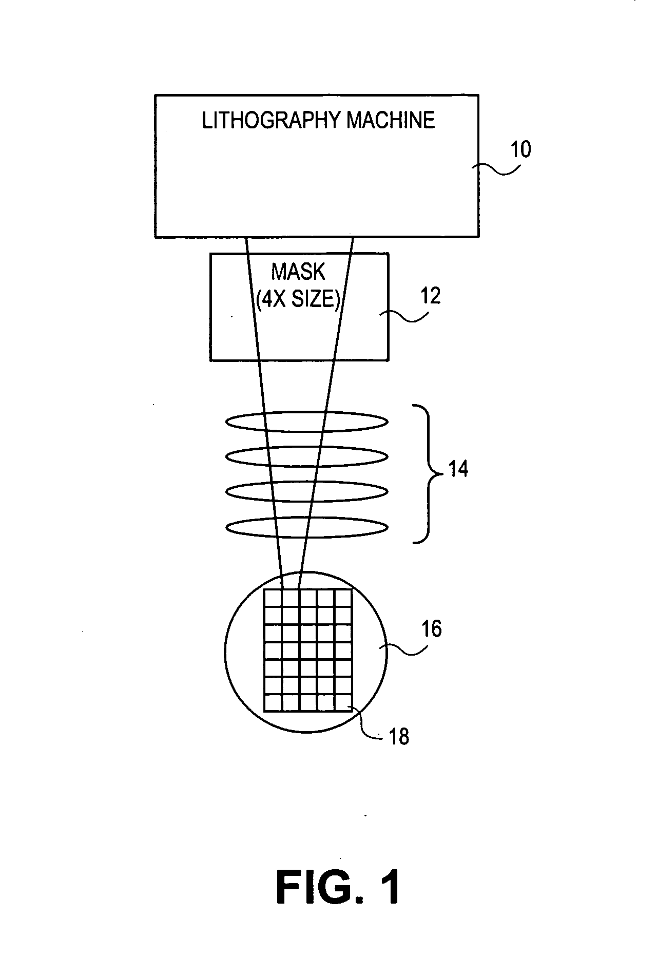
RELATED APPLICATIONS[0001]This application is related to co-pending U.S. patent application entitled, “Stencil Design and Method for Cell Projection Particle Beam Lithography”, Attorney Docket No. CA7049042001, filed concurrently herewith, the entire disclosure of which is expressly incorporated by reference herein.BACKGROUND[0002]1. Field[0003]The field of the present invention relates to particle beam lithography and, in particular, to combining and shaping cell patterns for improved particle beam efficiency.[0004]2. Description of Related Art[0005]In today's semiconductor manufacturing process, a common approach, as shown in FIG. 1, is the use of photo-lithography machines 10 and photo-lithography masks 12. In general, the mask 12 has an image for a layer of a chip that, through a series of lenses 14, is projected onto a wafer 16. Multiple chip images 18 are formed on the wafer 16 by stepping and repeating the mask image process across the surface of a wafer 16. The mask process ...

Claims


Application Information

Patent Timeline
Patent Type & Authority Applications(United States)
IPC IPC(8): G21K5/00
CPCB82Y10/00H01J37/3174B82Y40/00
Inventor FUJIMURA, AKIRAFONG, JAMESMITSUHASHI, TAKASHIMATSUSHITA, SHOHEI
Owner CADENCE DESIGN SYST INC
Learn More