Process for producing iii group nitride compound semiconductor light emitting device, iii group nitride compound semiconductor light emitting device and lamp

a technology of compound semiconductors and light emitting devices, which is applied in the direction of semiconductor devices, lasers, semiconductor lasers, etc., can solve the problems of poor crystallinity of buffer layers, inability to produce excellent crystallinity even if the method is stably used, and inability to provide excellent crystallinity

Active Publication Date: 2008-05-22
TOYODA GOSEI CO LTD
View PDF3 Cites 12 Cited by
  • Summary
  • Abstract
  • Description
  • Claims
  • Application Information

AI Technical Summary

Benefits of technology

[0026]As a result of thorough research conducted by the inventors of the present invention in order to solve the above problems, it has been discovered that it is possible to reproducibly realize the optimal balance between the mixed crystal composition and the dopant ...

Problems solved by technology

In general, there is a problem in that it is possible to grow a crystal epitaxially on a substrate when there is a lattice mismatching as in the above, and that it is impossible to provide a crystal having excellent crystallinity even if it is grown.
However, there is a problem in that an excellent crystal cannot be stably produced by the method disclosed in Patent Document 3.
However, since the methods disclosed in Patent Documents 4 and 5 form a buffer layer by a sputtering method, the resultant buffer layer may have poor crystallinity in terms of the conditions necessary for forming a layer, although the rate of forming layer is high.
When a GaN layer is grown up onto a buffer layer with such a low crystallinity by MOCVD method, there is possibility that the crystallinity of GaN layer sign...

Method used


Image

  • Process for producing iii group nitride compound semiconductor light emitting device, iii group nitride compound semiconductor light emitting device and lamp
  • Process for producing iii group nitride compound semiconductor light emitting device, iii group nitride compound semiconductor light emitting device and lamp
  • Process for producing iii group nitride compound semiconductor light emitting device, iii group nitride compound semiconductor light emitting device and lamp

Examples


example 1

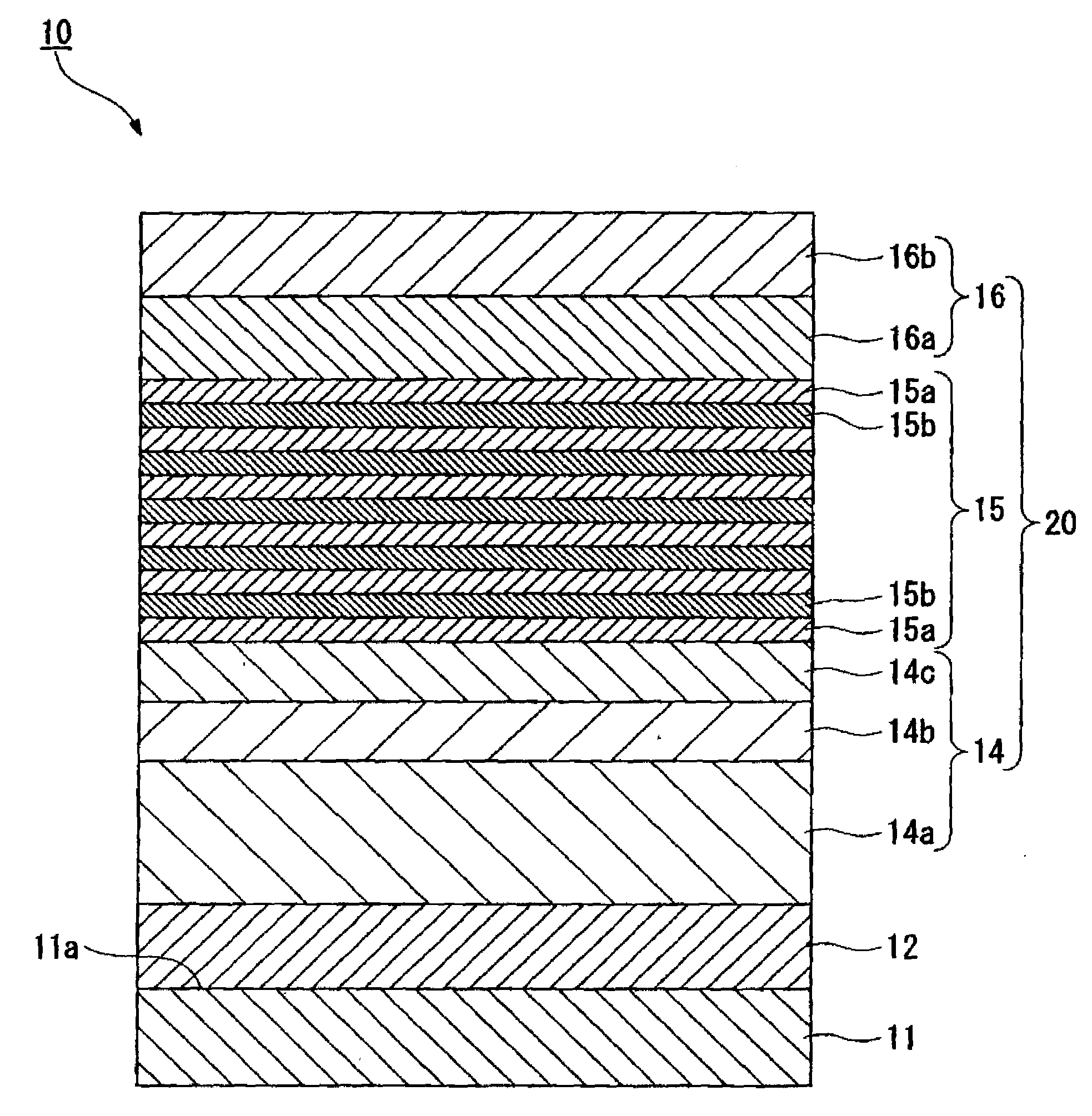
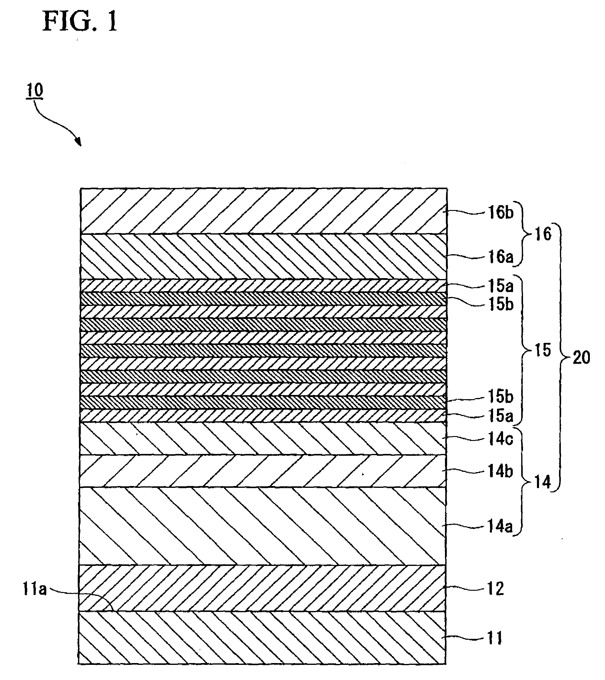
[0143]FIG. 1 is a schematic view showing a sectional structure of a laminated semiconductor of a group III nitride compound semiconductor light emitting device produced in this Example.

[0144]In this example, an aggregate of a columnar crystal consisting of AlN was formed on a c surface of the substrate 11 consisting of sapphire, as the buffer layer 12 using an RF sputtering method. Each of the ground layer 14a and the n-type contact layer 14b was formed as the n-type semiconductor layer 14 thereon using an RF sputtering method, and the n-type clad layer 14c was formed onto the n-type contact layer 14b using a MOCVD method. Also, the light emitting layer 15 was formed thereon using a MOCVD method, and then each of the p-type clad layer 16a and the p-type contact layer 16b was laminated in this order as the p-type semiconductor layer 16 onto the light emitting layer 15 using a sputtering method.

[0145]At first, the substrate 11 consisting of sapphire only one surface of which has been ...


PUM


Abstract

A process for producing a group III nitride compound semiconductor light emitting device, the group III nitride compound semiconductor light emitting device and a lamp, having excellent producability and excellent light emitting characteristics are provided. Such a process for producing a group III nitride semiconductor light emitting device is a process for producing a group III nitride semiconductor light emitting device having a semiconductor layer 20 constituted by laminating an n-type semiconductor layer, a light-emitting layer 15 and a p-type semiconductor layer 16. Each of these consists of a group III nitride semiconductor, including a step of forming at least a part of the semiconductor layer 20 by a sputtering method, in which upon forming the p-type semiconductor layer 14 by a sputtering method, a Ga target containing Ga element, and a dopant target consisting of a mixture of an element having a small crystal composition of elements contained in the p-type semiconductor layer 14 and a dopant element is used as a sputtering target, and power is applied simultaneously to both the Ga target and the dopant target.

Description

BACKGROUND OF THE INVENTION[0001]1. Field of the Invention[0002]The present invention relates to a group III nitride compound semiconductor light emitting device suitably used for a light emitting diode (LED), a laser diode (LD), an electronic device etc., and a group III nitride compound semiconductor light emitting device, and a lamp.[0003]Priority is claimed on Japanese Patent Application No. 2006-315497, filed Nov. 22, 2007, the content of which is incorporated herein by reference.[0004]2. Description of Related Art[0005]Since a group III nitride semiconductor light emitting device has a band gap of a direct transition type of energy corresponding to a range from visible light to ultraviolet rays, and excels in lumninous efficiency, a group III nitride semiconductor light emitting device is used as a light emitting device such as an LED or an LD.[0006]In addition, in the case in which a group III nitride semiconductor is used for an electronic device, it provides electronic devi...

Claims


Application Information

Patent Timeline
IPC IPC(8): H01L33/00H01L33/06H01L33/12H01L33/32H01L33/42H01L33/62
CPCB82Y20/00H01L21/0242H01L2924/3011H01L2224/73265H01L2224/49107H01L2224/48257H01L2224/48247H01L2224/48091H01L2224/32245H01L2224/45144H01S2304/04H01S5/34333H01L33/325H01L33/007H01L21/02631H01L21/02458H01L21/0254H01L21/02579H01L2924/00014H01L2924/00H01L2924/30111H01L2924/00012
Inventor MIKI, HISAYUKIHANAWA, KENZOSASAKI, YASUMASA
Owner TOYODA GOSEI CO LTD
Why Eureka
Try Eureka