Systems and methods for wireless power transfer

a wireless technology and wireless technology, applied in the field of electrical equipment, can solve the problems of inconvenient or safe opening of electrical contacts, inability to meet the needs of hard-wearing users, physical difficulty in implementing direct charging using wireless technology on existing portable devices, etc., and achieve the effect of satisfying users' requirements

Inactive Publication Date: 2008-05-22
BIO AIM TECH HLDG
View PDF4 Cites 227 Cited by
  • Summary
  • Abstract
  • Description
  • Claims
  • Application Information

AI Technical Summary

Benefits of technology

[0013]Embodiments of the invention can resolve the matter of cost, size and efficiency. Embodiments can be modular giving the possibility of for user to customize to their requirements with ease. It is flexible, where it can be mould to any shapes and sizes. It is also intelligent, it can detect when and where power is used, keeping auxiliary power losses to the minimum.

Problems solved by technology

Therefore, for consumers who own several of these devices are required to own or carry around several different types of adaptors which can be cumbersome when traveling or trying to find enough sockets to plug them into.
Moreover, these devices have open electrical contacts that can be damaged in water or exposed to other chemicals and therefore inappropriate to be used by hard wearing users.
With these devices for instant mobile phones, toothbrushes, PDA or laptop computers reliant on rechargeable secondary powered cells, it may not always be convenient or safe to have open electrical contacts.
However, direct charging is physically difficult to implement using wireless technology on existing portable devices.
Portable devices typically do not have room for any additional circuitry.

Method used


Image

  • Systems and methods for wireless power transfer
  • Systems and methods for wireless power transfer
  • Systems and methods for wireless power transfer

Examples


Embodiment Construction

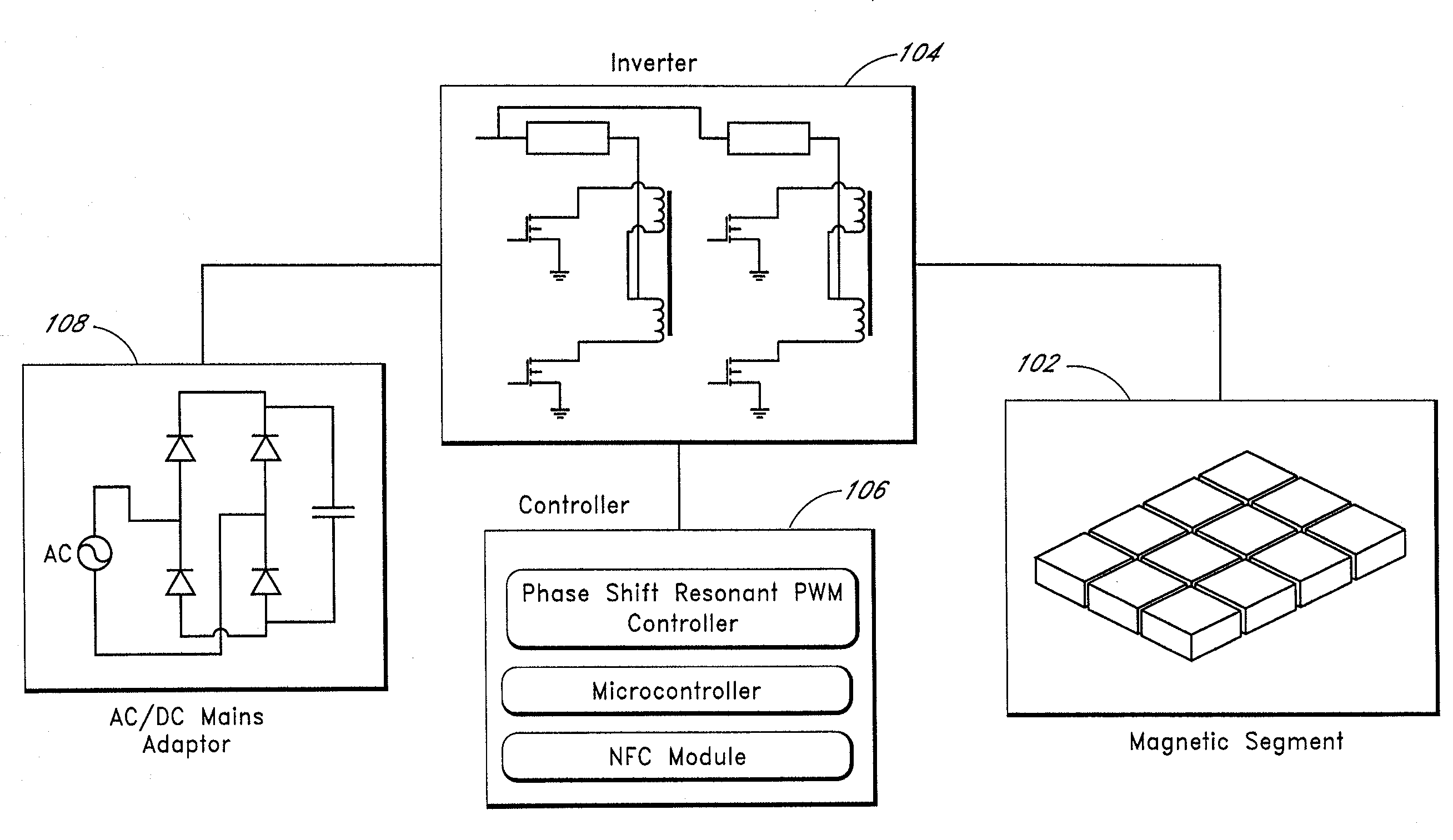
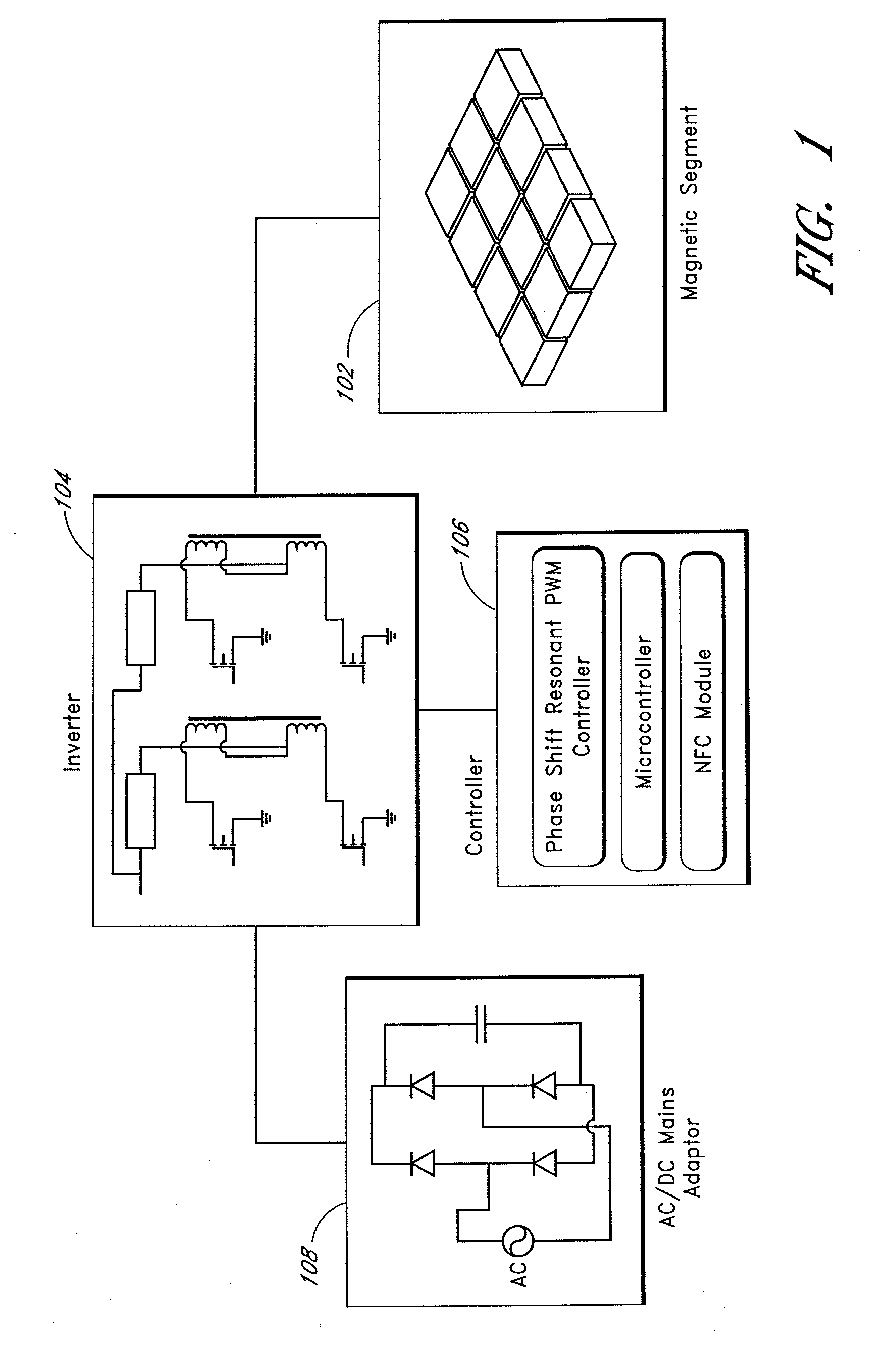
[0058]One embodiment is directed to a new generation is wireless power transfer. FIG. 1 illustrates one embodiment. The primary-side magnetic surface includes a mosaic of high-permeability micro-tiles. Cores for the micro tiles can be made from a high permeability material, such as ferrite. Other materials can be used. In one embodiment, the relative permeability of the material for the core is at least 20.

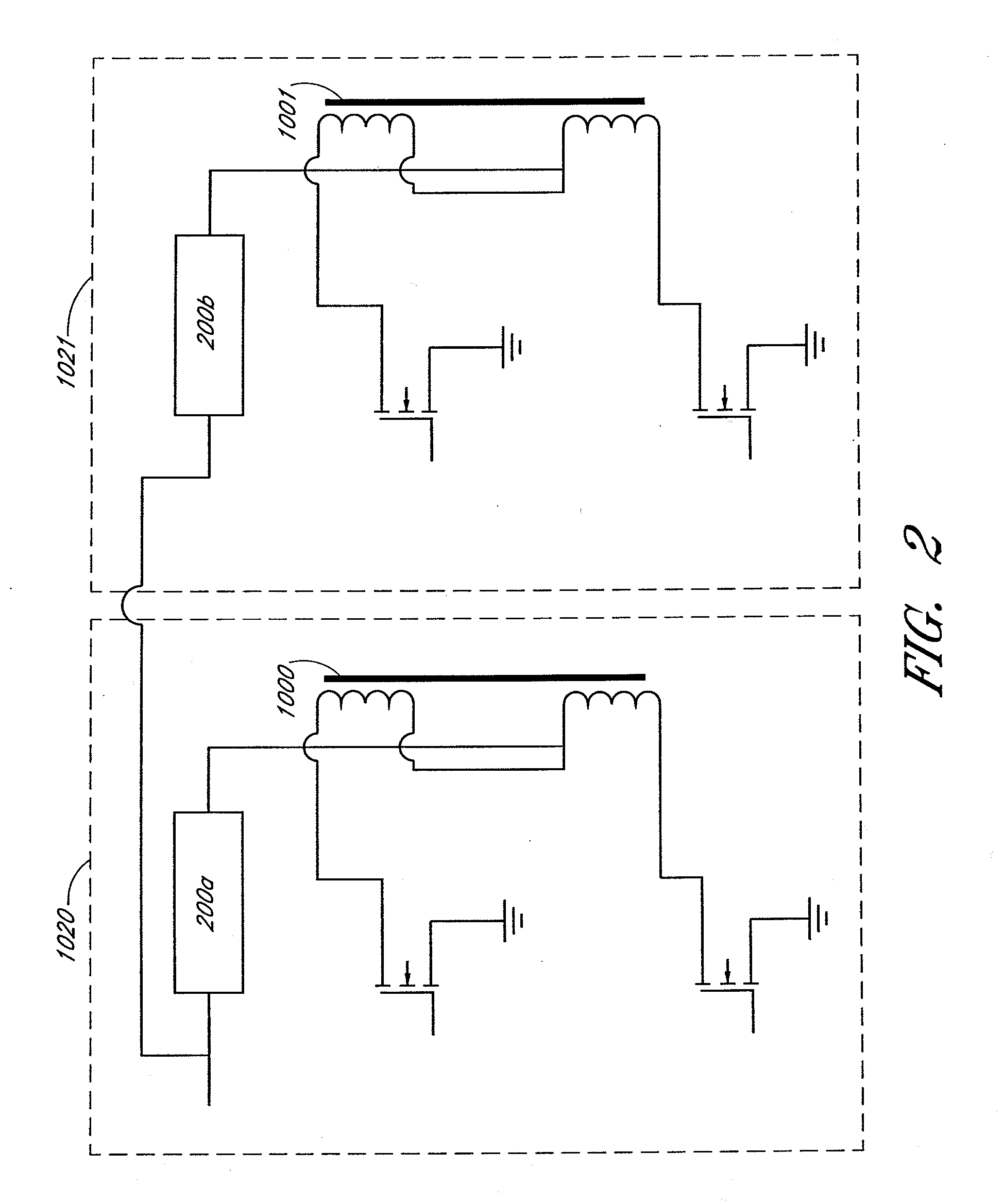
[0059]The use of 12 tiles is for illustrative purposes and is not intended to be limiting. These tiles can vary in size, for example, between 3-5 mm in thickness, and 10-20 mm in length and width. These dimensions are intended to be illustrative and not necessarily limiting. These micro-tiles form a magnetic segment 102 or array of micro-tiles. This segment 102 is powered by a switched mode power electronics circuitry, which includes an inverter 104 and a control system 106. The switched mode power electronics circuitry in turn receives a DC input from the mains adapter 108 which ...


PUM

PropertyMeasurementUnit
lengthaaaaaaaaaa
thicknessaaaaaaaaaa
thicknessaaaaaaaaaa

Abstract

Systems and methods for wireless power transfer are disclosed. Primary windings generate magnetic fields which are inductively coupled to secondary windings to transfer power in a wireless manner. One embodiment includes a plurality of tiles of magnetic cores and windings for the primary windings. The tiles can be arranged in a magnetic segment with windings of tiles being orthogonal with respect to windings of adjacent tiles. For example, a winding of a first tile can be horizontal, and windings of adjacent tiles can be vertical. One embodiment further groups these magnetic segments into larger entities, wherein each magnetic segment can be independently activated. One embodiment includes a magnetic amplifier or an electronic device for secondary side control of power. This permits multiple devices to be powered or charged to be able to regulate power or charging independently from one another.

Description

CROSS-REFERENCE TO RELATED APPLICATIONS[0001]This application claims the benefit under 35 U.S.C. § 119(e) of U.S. Provisional Application No. 60 / 841,759, filed on Sep. 1, 2006; U.S. Provisional Application No. 60 / 894,581, filed on Mar. 13, 2007; and U.S. Provisional Application No. 60 / 950,192, filed on Jul. 17, 2007, the entire disclosures of which are hereby incorporated by reference.[0002]This application is related to copending application titled THREE-DIMENSIONAL ELECTROMAGNETIC FLUX FIELD GENERATION, Ser. No. ______ [Attorney Docket No. RAIF.004A], filed on the same date as the present application, the entirety of which is hereby incorporated by reference.BACKGROUND OF THE INVENTION[0003]1. Field of the Invention[0004]The invention generally relates to electronics, and in particular, to wireless charging.[0005]2. Description of the Related Art[0006]Portable devices has proliferated over the past ten years. For the purpose of cost and convenience these devices rely on secondary ...

Claims


Application Information

Patent Timeline
Patent Type & Authority Applications(United States)
IPC IPC(8): H02J7/00H01F38/00
CPCH02J7/025H02J5/005H02J7/00308H02J50/80H02J50/60H02J50/10H02J50/70H02J50/12
Inventor LOKE, SIEW LINGLEE, ENG HUAAWAIDA, RAIF M.
Owner BIO AIM TECH HLDG
Why Eureka
Try Eureka