Secondary Battery Protection Circuit, Battery Pack and Thermosensitive Protection Switch Device

a protection circuit and secondary battery technology, applied in the direction of safety/protection circuits, batteries, cell components, etc., can solve the problems of increasing the circuit size of the protection circuit, increasing costs, and inconvenience of enlarging the fets, so as to reduce the characteristic degradation of the secondary battery and simplify the circuit

Inactive Publication Date: 2008-05-22
PANASONIC CORP
View PDF4 Cites 100 Cited by
  • Summary
  • Abstract
  • Description
  • Claims
  • Application Information

AI Technical Summary

Benefits of technology

[0027]With this construction, if the physical quantity relating to the characteristic of the secondary battery exceeds the preset value, the first heater is caused to generate heat by the protection controller and the heat-sensitive switch is heated by the first heater, thereby turning the heat-sensitive switch off to cut off a charge or discharge current. Thus, the characteristic degradation of the secondary battery can be reduced. Further, since the discharge current and the charge current can be cut off by one heat-sensitive switch, the circuit can be simplified.

Problems solved by technology

This has caused inconvenience of increasing the circuit size of the protection circuit 1002.
Particularly if it is necessary to cause a large load current to flow as in the battery pack 1141 shown in FIG. 54, transistors with a large current rating need to be used as the FETs 1149, 1150, which has caused inconvenience of enlarging the FETs 1149, 1150 and increasing costs.
However, since the transistors having high withstand voltages tend to increase the on-resistances, there has been inconvenience of increasing power losses in the FETs 1149, 1150.
Thus, if the secondary battery continues to be charged with such a charge current as not to suddenly increase temperature as in the case where a battery pack is charged, for example, using a charger having poor accuracy in controlling the charging voltage, the secondary battery is overcharged without the temperature switch operating, thereby causing inconvenience of degrading the characteristics of the secondary battery and leading to a likelihood of expanding or deforming the battery.

Method used


Image

  • Secondary Battery Protection Circuit, Battery Pack and Thermosensitive Protection Switch Device
  • Secondary Battery Protection Circuit, Battery Pack and Thermosensitive Protection Switch Device
  • Secondary Battery Protection Circuit, Battery Pack and Thermosensitive Protection Switch Device

Examples


first embodiment

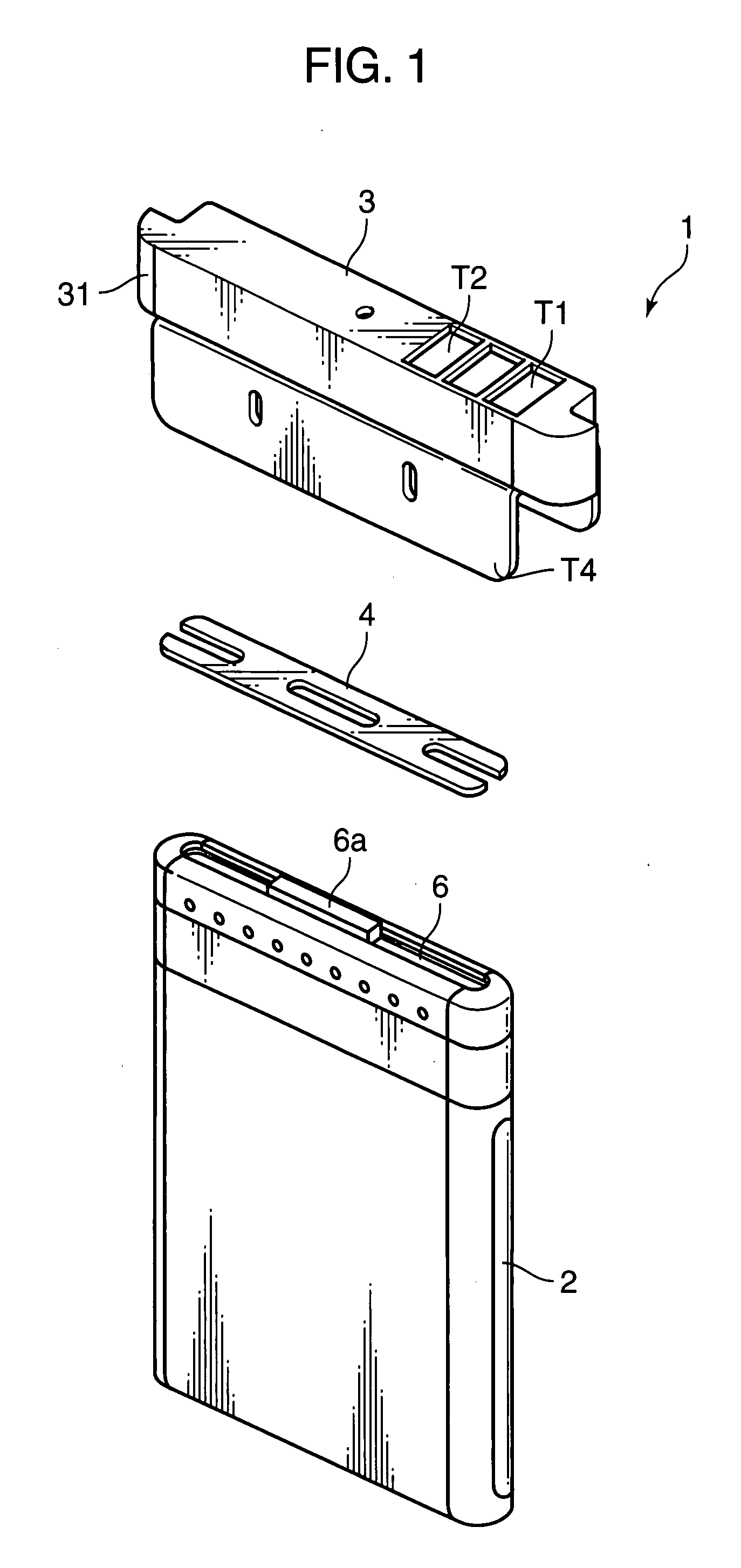
[0083]FIG. 1 is an exploded perspective view showing one example of a battery pack according to one embodiment of the present invention. A battery pack 1 shown in FIG. 1 is provided with a container 2 in the form of a bottomed tube, an external terminal connecting unit 3, and a plate-shaped spacer 4 to be inserted between the container 2 and the external terminal connecting unit 3. A secondary battery 6 is accommodated into the container 2 and sealed by caulking, and a positive electrode terminal 6a projecting from the secondary battery 6 projects through an opening end of the container 2. The container 2 is made of a steel sheet having the outer surface nickel plated, and a negative electrode of the secondary battery 6 is connected with the container 2 inside the container 2.

[0084]The external terminal connecting unit 3 includes a casing 31 formed, for example, by resin molding, and connection terminals T1, T2 used to connect a charging device and load devices are exposed on the ou...

second embodiment

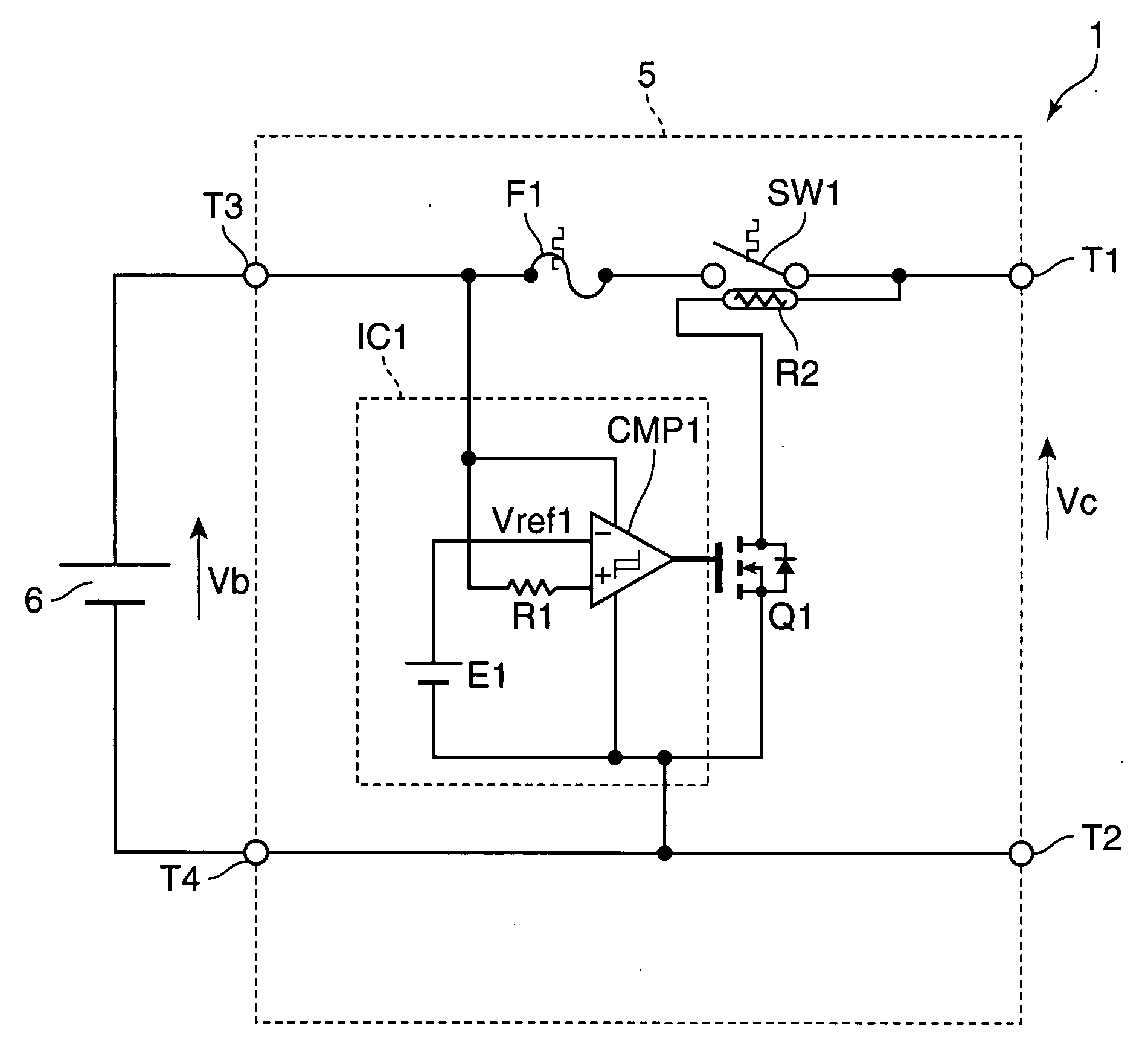
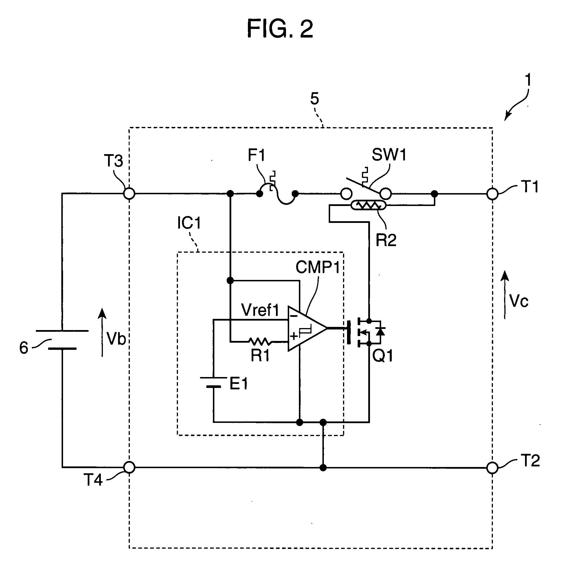
[0114]Next, a battery pack according to a second embodiment of the present invention is described. The external appearance of a battery pack 1a according to the second embodiment of the present invention is similar to that of the battery pack 1 shown in FIG. 1. Further, the electrical construction of a protection circuit 5a provided in the battery pack 1a according to the second embodiment of the present invention is similar to the protection circuit 5 shown in FIG. 2, but the mechanical construction thereof differs from that of the protection circuit 5 shown in FIG. 4.

[0115]FIG. 5 are schematic diagrams showing the mechanical construction of the protection circuit 5a according to the second embodiment of the invention, wherein FIG. 5A is a diagram showing wiring patterns used to mount components of the protection circuit 5 and FIG. 5B is a section showing one example of the mechanical construction of the protection circuit 5. FIG. 6A is a top view of the protection circuit 5 shown ...

third embodiment

[0135]FIG. 9 is a circuit diagram showing one example of the electrical construction of a battery pack 1b according to a third embodiment of the present invention. The battery pack 1b shown in FIG. 9 is used for an electric device, in which a large load current, e.g. 100 A (1 kW) flows, such as an electric tool, an electric automobile or a robot and for a super-rapid charge standard cell to be charged within a short time of about several minutes. The battery pack 1b shown in FIG. 9 differs from the battery pack 1 shown in FIG. 2 in that secondary batteries 62 to 65 connected in series are provided in place of the secondary battery 6 and an integrated circuit IC2 is provided in place the integrated circuit IC1. In this case, the integrated circuit IC2 corresponds to one example of the protection controller and a wiring pattern connecting the integrated circuit IC2, the temperature fuse F1 and the secondary battery 62 corresponds to one example of the first connection terminal.

[0136]T...


PUM

PropertyMeasurementUnit
currentaaaaaaaaaa
temperatureaaaaaaaaaa

Abstract

A protection circuit is provided for protecting a secondary battery from overcharging and excessive discharge current by a simple circuit. The protection circuit is provided with a connection terminal (T3) for connecting the secondary battery (6); a connection terminal (T1) for connecting a charging device for charging the secondary battery (6) and/or a load device driven by a discharge current from the secondary battery (6); a bimetal switch (SW1) that is provided between the connection terminals (T1, T3) and turned off in the case of exceeding a specified temperature set beforehand; a heater (R2) for heating the bimetal switch (SW1); and an integrated circuit (IC1) for turning the bimetal switch (SW1) off by causing the heater (R2) to generate heat if a voltage applied to the connection terminal (T3) by the secondary battery (6) exceeds a preset reference voltage.

Description

FIELD OF TECHNOLOGY[0001]The present invention relates to a protection circuit for protecting a secondary battery from overcharging and excessive discharge current, a thermosensitive protection switch device and a battery pack provided with such protection circuit and switch device.BACKGROUND ART[0002]FIG. 51 is a circuit diagram showing the construction of a battery pack according to background art. A battery pack 1001 shown in FIG. 51 is provided with a protection circuit 1002 and a secondary battery 1003. The secondary battery 1003 is, for example, a rechargeable secondary battery such as a lithium ion secondary battery, a lithium polymer secondary battery, a nickel-metal-hydride secondary battery or a nickel-cadmium secondary battery. In the case of overcharging or excessive discharge current, such a secondary battery might have characteristics thereof such as cycle life degraded or might undergo expansion, deformation and the like. Accordingly, the battery pack 1001 is provided...

Claims


Application Information

Patent Timeline
Patent Type & Authority Applications(United States)
IPC IPC(8): H02H7/18H02J7/00H01M50/583
CPCH01M2/34H01M2/348H02J7/0031H01M2200/106H01M10/443Y02E60/10H01M50/581H02J7/00302H02J7/00309H02J7/00306H01M50/583
Inventor MORI, IICHIRO
Owner PANASONIC CORP
Why Eureka
Try Eureka