Optical measurement apparatus
- Summary
- Abstract
- Description
- Claims
- Application Information
AI Technical Summary
Problems solved by technology
Method used
Image

Examples
first embodiment
[0039] Preferred embodiments of the invention will be described with reference to the drawings.
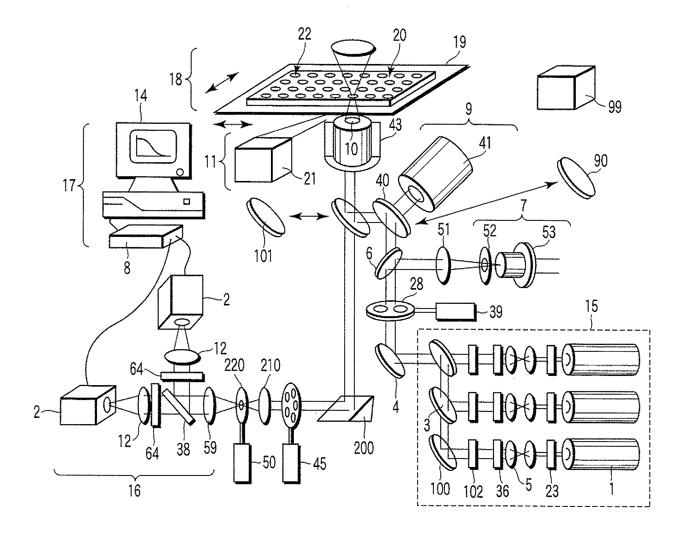
[0040]FIG. 1 shows a basic configuration of an optical measurement apparatus according to a first embodiment of the invention.
[0041] The optical measurement apparatus of the first embodiment mainly includes a light source unit 15, a light quantity monitoring mechanism 7, a beam scanning apparatus 9, an objective lens 10, a solution immersion feeding mechanism 11, a sample retaining mechanism 18, an optical detection unit 16, and a signal processing unit 17.
[0042] The detailed configuration and operation of the optical measurement apparatus will be described below.
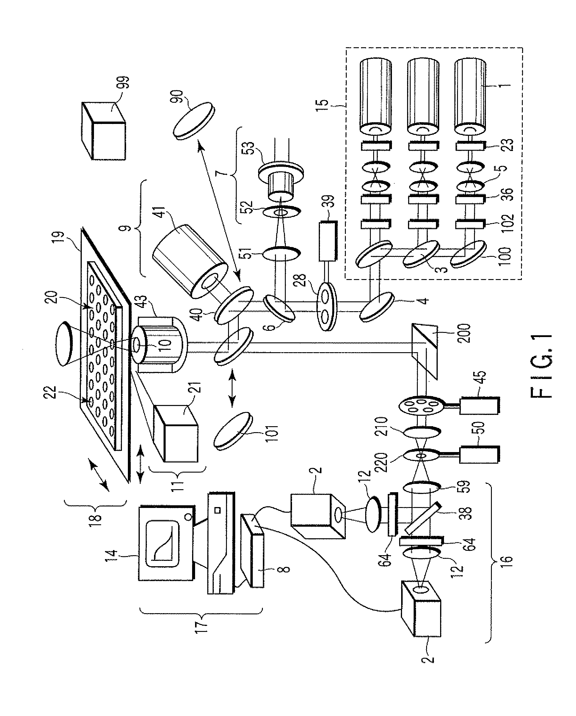
[0043] A laser beam source 1, a shutter 23, a beam diameter changing mechanism 5, a rotary ND filter 36, a beam shifter 102, a mirror 100, and a dichroic mirror 3 are provided in the light source unit 15.
[0044] Three kinds of the laser beam sources 1 are provided in the light source unit 15. A helium-neon laser (oscillation o...
first modification
[0101]FIG. 10 shows a first modification of the first embodiment. In the first modification, the measurement apparatus is unitized in a light source unit, a measurement apparatus main body unit, and a light acceptance unit, the units are optically connected to one another using optical fibers 24 and 80 to achieve downsizing of the measurement apparatus. The first modification is similar to the first embodiment except that the single-mode optical fiber 24 and the multi-mode optical fiber 80 are used to transmit the light in the light source and light acceptance unit respectively. Accordingly, the same component as the first embodiment is designated by the same numeral, and the description of the basic apparatus configuration and operation is omitted.
[0102] The light sources 1 are disposed in the light source unit 15 separated from the measurement apparatus main body. An optical fiber light acceptance terminal 49 is irradiated with the laser beam emitted from each of the light source...
second modification
[0109]FIG. 14 shows a second modification of the first embodiment. Similarly to the first modification, the second modification has the configuration in which the measurement apparatus main body and the light source unit are separated from each other. Accordingly, the same component as the first embodiment is designated by the same numeral, and the description of the basic apparatus configuration and operation is omitted.
[0110] A ferrule-type optical element 48 is used in a light introduction unit to the measurement apparatus main body from the light source unit 15 including the plural laser beam sources 1. The ferrule-type optical element 48 is formed by a solid body, and the ferrule-type optical element 48 accepts the incident light and outputs the outgoing light. Therefore, a point light source can equivalently be generated at the position of the measurement apparatus main body.
[0111]FIG. 15 shows a configuration of the ferrule-type optical element 48. In the ferrule-type optic...
PUM
 Abstract
Description
Claims
Application Information
 - Generate Ideas
- Intellectual Property
- Life Sciences
- Materials
- Tech Scout
- Unparalleled Data Quality
- Higher Quality Content
- 60% Fewer Hallucinations
Browse by: Latest US Patents, China's latest patents, Technical Efficacy Thesaurus, Application Domain, Technology Topic, Popular Technical Reports.
© 2025 PatSnap. All rights reserved.Legal|Privacy policy|Modern Slavery Act Transparency Statement|Sitemap|About US| Contact US: help@patsnap.com