[0013] In another preferred example of embodiment, the handgrip comprises a first end, at which the connection device for the filling compound container is provided and at which one or more
light emission areas of the light emission device can be or are also disposed. To
advantage, therefore, the use of the handgrip is additionally facilitated for the dentist. The light emission device can either be provided fixed in the region of the first end, or it can also be arranged so as to be mobile, for example displaceable in the handgrip, so that it can be moved if need be in the direction of the first end or up to the first end or beyond it.
[0014] In order to prevent the user from inadvertently delivering filling compound from the filling compound container and directing the light emission device onto the filling compound at the same time, so that for example an undesired, at least partial hardening of the filling compound takes place before the latter has been introduced in the optimum manner into the tooth cavity, the handgrip is provided with a safety device or means to prevent a premature or inadvertent light emission onto the filling compound. These safety means can have the most diverse embodiments, whereby a dental handgrip could have one or more of these safety means. The aim of these safety means is to prevent light from striking the filling compound before the user intends to harden the filling compound, or at least to ensure that the
radiant energy or intensity of the light striking the filling compound is so small that a premature hardening reaction caused by the light emission device and disadvantageous to the patient does not take place before the actual hardening is intentionally started by the dentist.
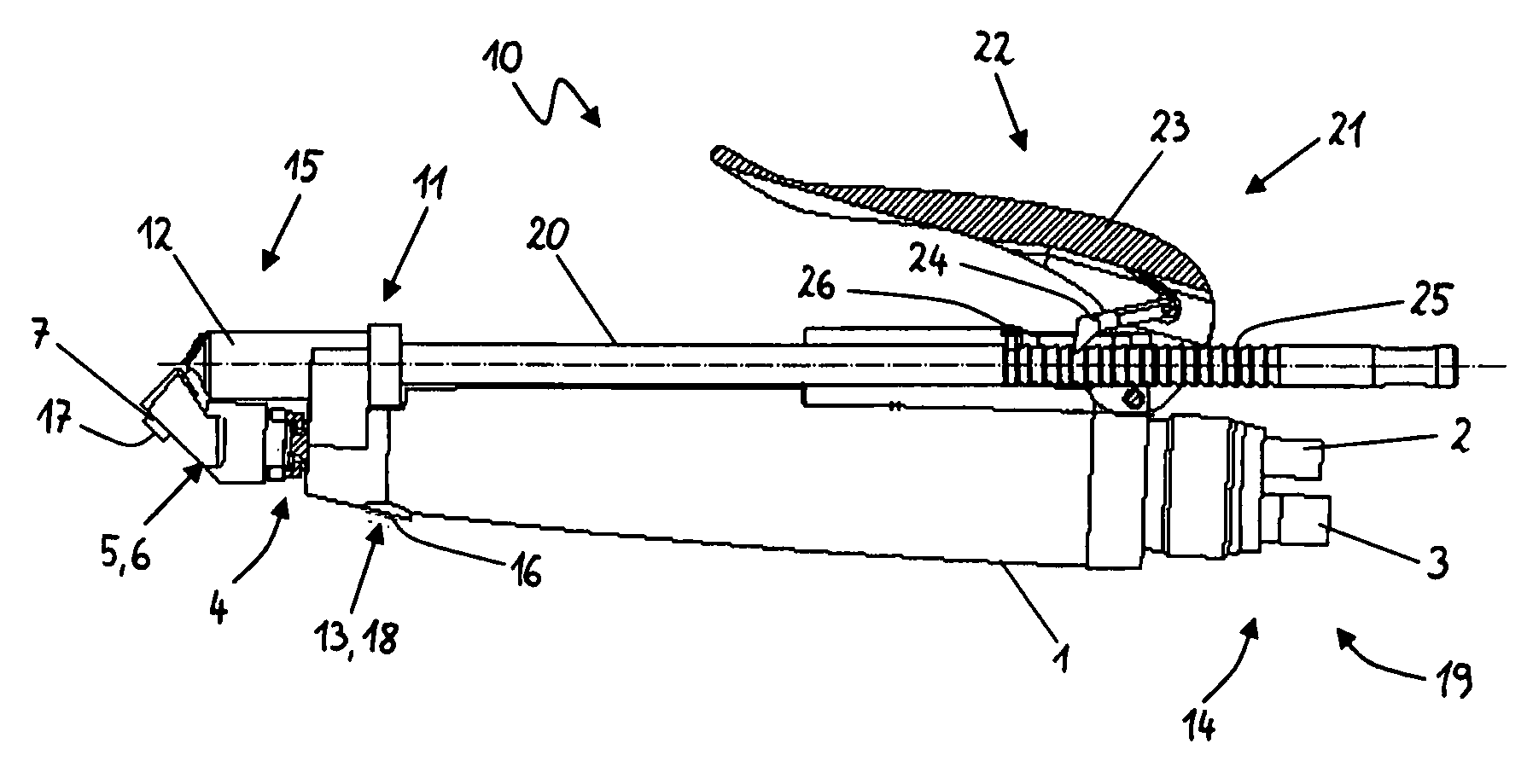
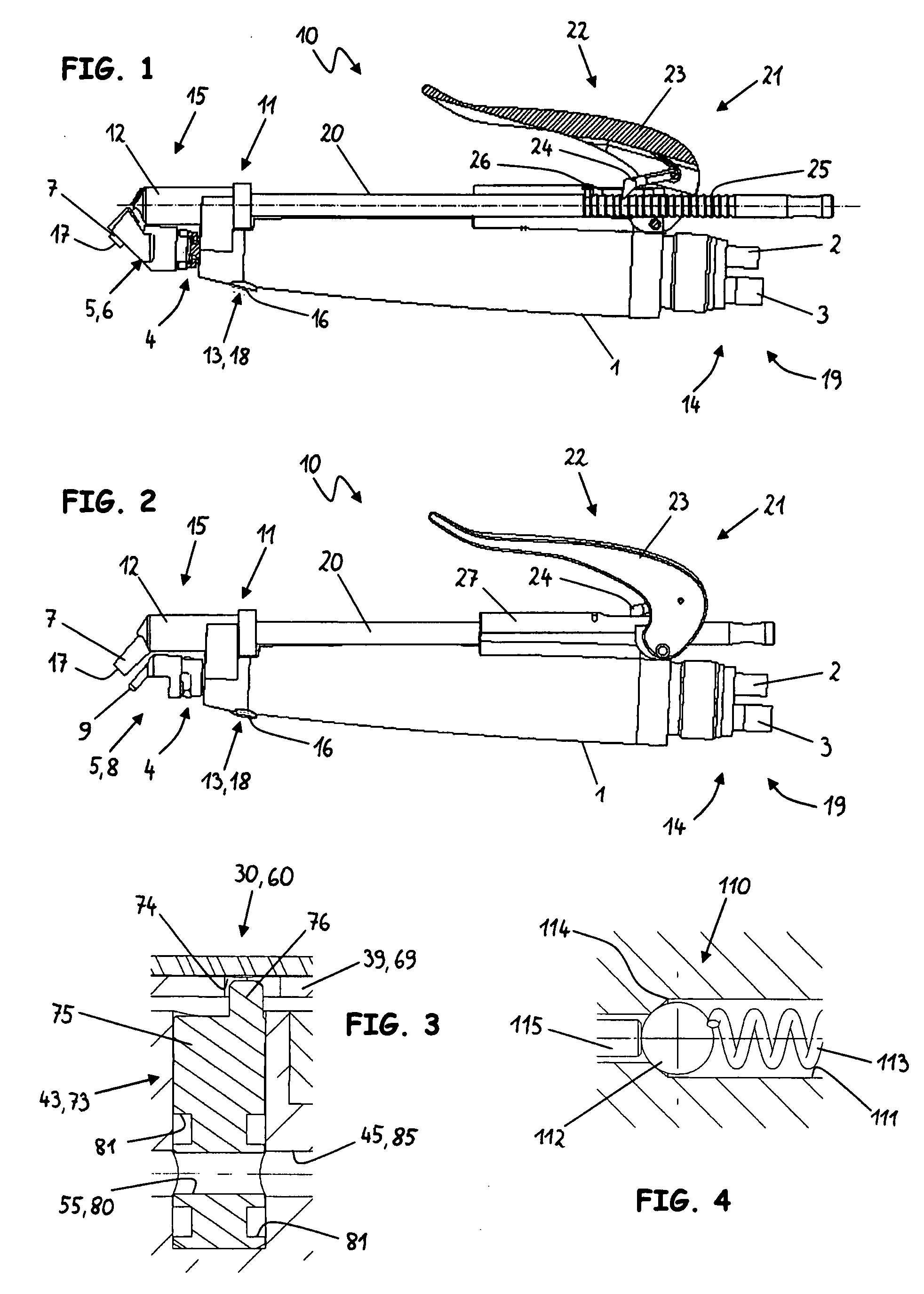
[0015] In a first exemplary embodiment, the safety means comprise the light emission area(s) of the light emission device and the delivery opening(s) of the filling compound container, the light emission area(s) and the delivery opening(s) being disposed in such a way that they point in different directions. Alternatively, or additionally, a device, in particular a mechanical device, for example a rotatable or swivelling cover device, can be provided, which is designed in such a way that either only the light emission area(s) or the delivery opening(s) is / are free, so that only light or filling compound can be delivered, whereas the other of the two elements (light emission area or delivery opening) is covered. Instead of the covering of the light emission area, the device can also be designed such that at least the major part of the light emitted by the light emission device is deflected, shielded or absorbed. The essential point is that the means are designed in such a way that no light can arrive at the filling compound as long as this is not desired by the user, or that only so little light strikes the filling compound that it does not lead to a premature, undesired hardening reaction.
[0018] According to a second aspect, a dental handgrip for the delivery of filling compound with a fluid-operated delivery device for delivering the filling compound from the filling compound container is disclosed, the supply for the handgrip with the driving fluid preferably taking place via an external fluid source. A compressed gas, in particular
compressed air, or a liquid, in particular water, can be used as the driving fluid. A
coupling element for connecting the delivery device to an external fluid source is preferably also provided on the handgrip, the
coupling element particularly preferably being designed in such a way that it can be coupled to a counter-
coupling element, which is provided for the connection to a dental hand-held instrument with another function. If the counter-coupling element is part of a dental unit, the quantity of the air fed to the delivery device can be controlled by means of a foot control which is connected to the dental unit. To
advantage, the effect of this is that the delivery takes place uniformly and automatically, without the user having to carry out a delivery operation, such as for example operating a lever. All the operating elements for the delivery are not therefore required on the handgrip, so that the user has a better view of the preparation site.
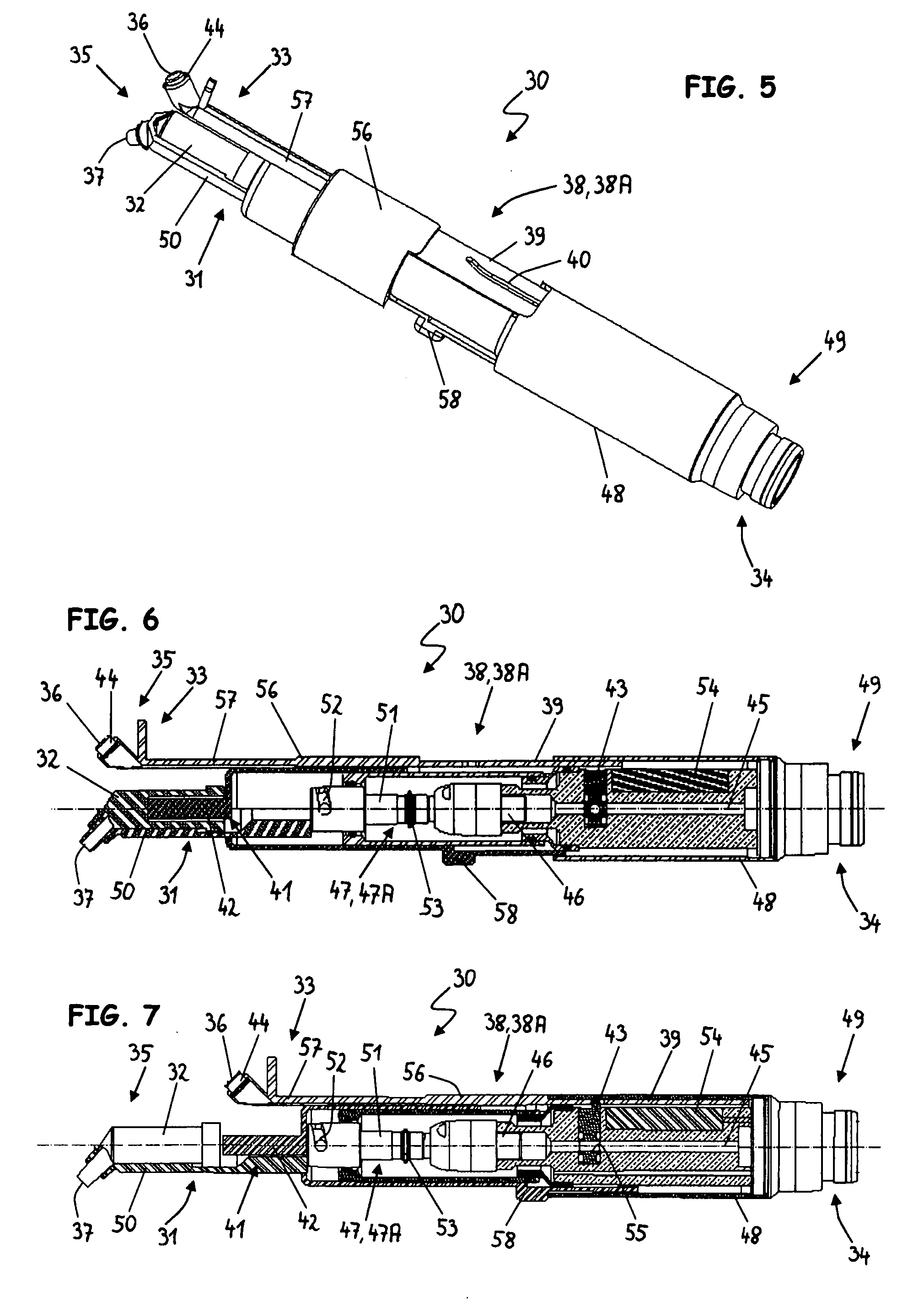
[0019] In another exemplary embodiment, the handgrip comprises a vibration generator, which can be or is connected directly or indirectly to the connection device, so that the vibration generated by the vibration generator can be transmitted to the filling compound, as a result of which the
viscosity of the filling compound is reduced and the filling compound can be delivered more easily. The vibration generator is designed as a fluid-operated vibration generator. The vibration generator and the delivery device are preferably connected to one another directly or indirectly, for example via the hollow vibration shaft of the vibration generator, so that at least a part of the fluid can be used for the operation of the delivery device and the vibration generator. A handgrip according to this embodiment is constructed very simply and compactly, especially in terms of production and
assembly, as a result of which the production and
assembly costs can be significantly reduced. Such a handgrip also uses the driving fluid effectively and sparingly. The connection between the vibration generator and the delivery device can of course also take place via one or more lines, channels, holes or other elements. The connection can also contain other functional elements, such as for example valves, in particular for the
pressure control.

