Wavelength shifting lightguides for optimal photodetection in light-sharing applications

a lightguide and wavelength shifting technology, applied in the field of nuclear medical imaging, can solve the problems of difficult to make scintillator materials with good pet properties, and not well matched for use with other types of photodetectors

Inactive Publication Date: 2008-05-29
SIEMENS MEDICAL SOLUTIONS USA INC
View PDF9 Cites 9 Cited by
  • Summary
  • Abstract
  • Description
  • Claims
  • Application Information

AI Technical Summary

Problems solved by technology

LSO is a very good scintillator for PET because of its high density, high light output, and non-hygroscopic characteristics, but it is not well matched for use with other types of photodetectors, such as avalanche photodiodes (APDs), silicon photomultipliers (SiPMs), or other solid-state based photodetectors.
It is difficult to make a scintillator material with good PET properties and to make it emit at a certain desired wavelength.

Method used


Image

  • Wavelength shifting lightguides for optimal photodetection in light-sharing applications
  • Wavelength shifting lightguides for optimal photodetection in light-sharing applications
  • Wavelength shifting lightguides for optimal photodetection in light-sharing applications

Examples


second embodiment

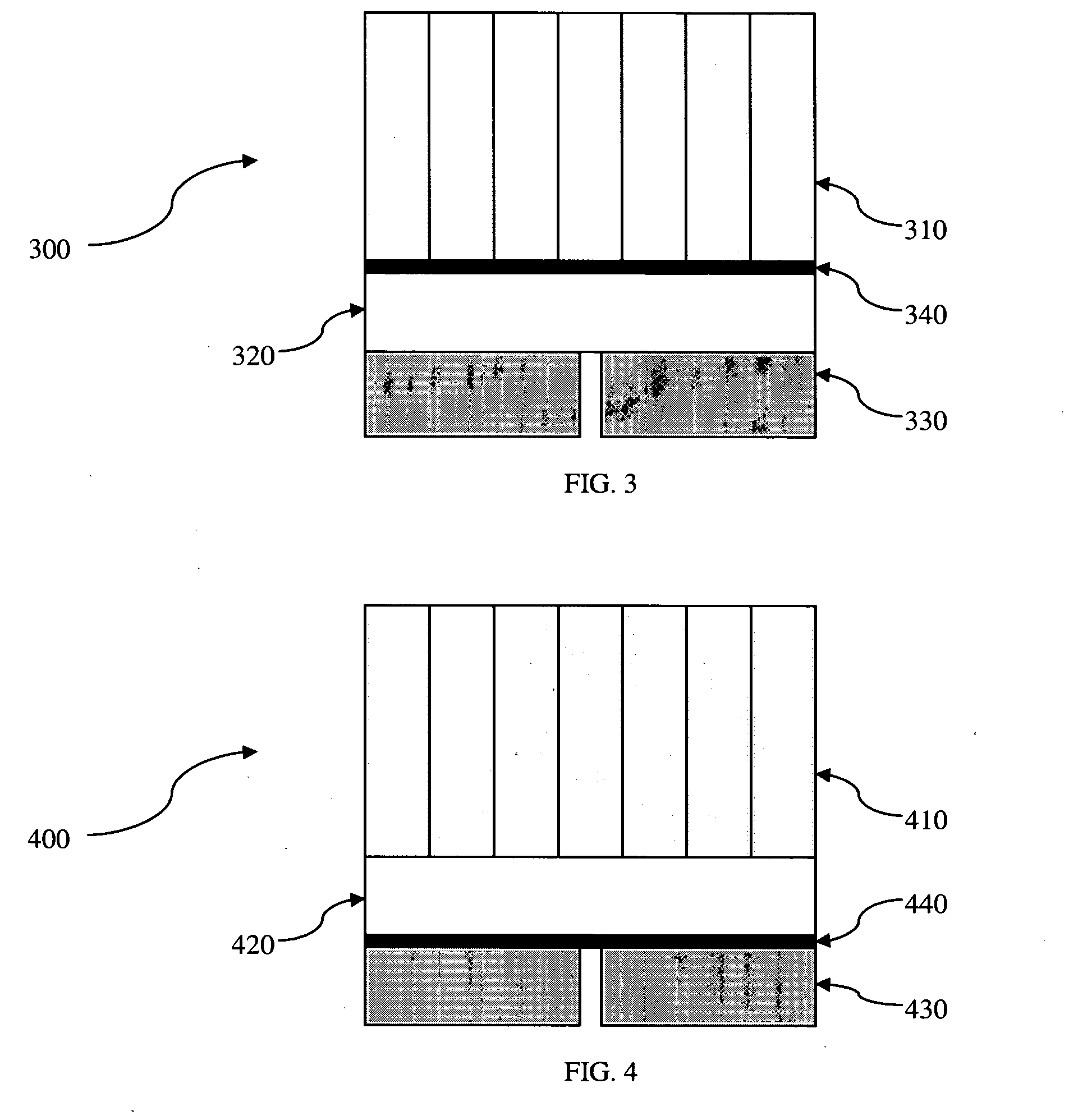
[0022]FIG. 3 depicts the invention in the form of block detector 300. Block detector 300 includes a scintillator array 310. The light emitted from scintillator array 310, in response to interaction with a gamma ray, may pass through a wavelength shifting coating 340 on the entry surface of an optical lightguide 320. As the light passes through wavelength shifting coating 340, the wavelength increases as the energy of the light photons is partially dissipated in the wavelength shifting coating. The coating may be a wavelength shifting chemical, a dye, a plastic, or any other wavelength shifting material. The light is then transmitted through lightguide 320 to photodetectors 330.

third embodiment

[0023]FIG. 4 depicts the invention in the form of block detector 400. Block detector 400 includes a scintillator array 410. The light emitted from scintillator array 410, in response to interaction with a gamma ray, is transmitted through optical lightguide 420. As the light exits lightguide 420, it passes through a wavelength shifting coating 440 on the exit surface of lightguide 420. As the light passes through wavelength shifting coating 440, the wavelength increases. The coating may be a wavelength shifting chemical, a dye, a plastic, or any other wavelength shifting material. The light then reaches photodetectors 430.

[0024]FIG. 5 is a graph showing the ranges of an absorption spectrum 510 and an emission spectrum 520 of a typical wavelength shifting material BC-482A made by Saint Gobain. Such wavelength shifting material may have an absorption peak at 420 nm and an emission peak at 494 nm. If such a material were used in place of an optical lightguide it would increase the ligh...


PUM


Abstract

A scintillation detector for PET imaging devices includes a wavelength shifting material for shifting the emission wavelength of a scintillator toward the peak wavelength sensitivity of a photodetector array coupled to receive light from the scintillator. Preferably the scintillator is an LSO scintillator and the photodetector array is a silicon-based array such APDs or SiPMs.

Description

TECHNICAL FIELD[0001]The present invention relates to the field of nuclear medical imaging, such as Positron Emission Tomography (PET). In particular, the present invention relates to improvements in light collection efficiency of PET detectors.BACKGROUND OF THE INVENTION[0002]Medical imaging is one of the most useful diagnostic tools available in modern medicine. Medical imaging allows medical personnel to non-intrusively look into a living body in order to detect and assess many types of injuries, diseases, conditions, etc. Medical imaging allows doctors and technicians to more easily and correctly make a diagnosis, decide on a treatment, prescribe medication, perform surgery or other treatments, etc.[0003]In traditional PET imaging, a patient is injected with a radioactive substance with a short decay time. As the substance undergoes positron emission decay, it emits positrons which, when they collide with electrons in the patient's tissue, emit two high energy (e.g. 511 keV), si...

Claims


Application Information

Patent Timeline
Patent Type & Authority Applications(United States)
IPC IPC(8): G01T1/164G01T1/20
CPCG01T1/2018G01T1/20G01T1/20185
Inventor GRAZIOSO, RON
Owner SIEMENS MEDICAL SOLUTIONS USA INC
Why Eureka
Try Eureka