Frequency-optimized detection of gun muzzle flashes

Active Publication Date: 2008-05-29
SOUTHWEST RES INST
View PDF1 Cites 5 Cited by
  • Summary
  • Abstract
  • Description
  • Claims
  • Application Information

AI Technical Summary

Problems solved by technology

Although some modeling and observations have been reported, analysis has been crude and observations have been few.
As a result, it is no

Method used


Image

  • Frequency-optimized detection of gun muzzle flashes
  • Frequency-optimized detection of gun muzzle flashes
  • Frequency-optimized detection of gun muzzle flashes

Examples


Embodiment Construction

I. Overview

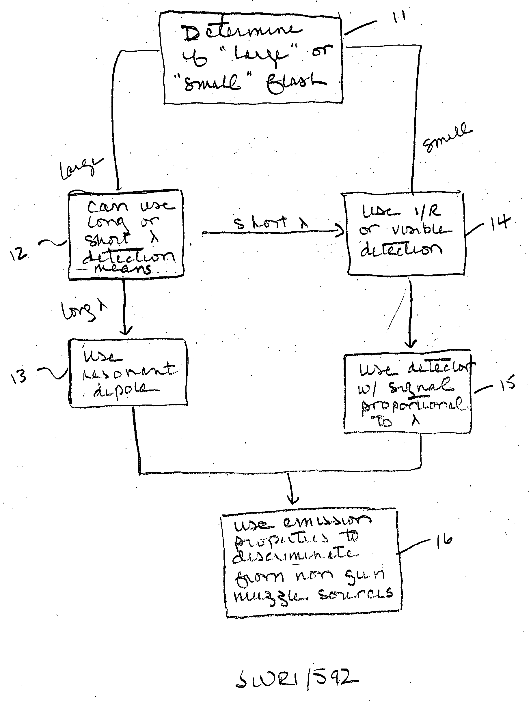
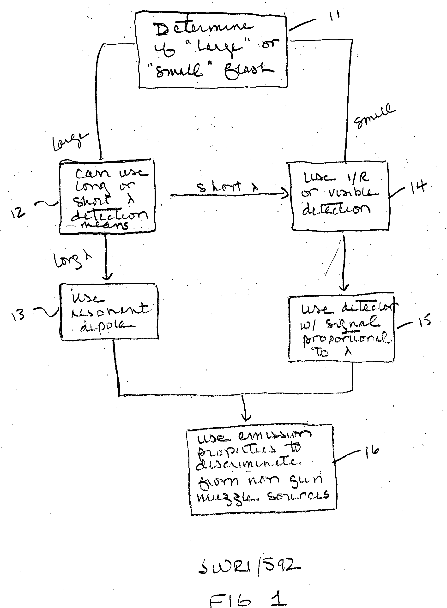
[0007]The following description is directed to a method in which remote detection of gunfire is achieved by means of the electromagnetic waves emitted by the muzzle flash. For large cannon, detection can be at low as well as at high frequencies. For small arms fire, detection is in the IR and visible wavelengths to capitalize on the increased power emitted at the higher frequencies. At IR frequencies, IR detectors that give signals proportional to detector area may be used (e.g. bolometric-type), which avoids the inverse squared frequency penalty imposed by the use of resonant antennas. For the same reason, at visible frequencies, optical-type detectors with sensitivities proportional to detector area (e.g. photodiodes) can be used. Arrays and lens- or mirror-telescopic detection systems may be used to increase sensitivity and directionality.

[0008]Detectors at short (visible and IR) wavelengths do not suffer from the inverse squared frequency dependence of resonant antenn...


PUM


Abstract

Methods for remotely detecting a gun muzzle flash, using frequency-optimized detection methods. Small explosive charges are best detected at I/R and visible wavelengths, using optical detectors, whereas large explosive charges may also be detected with antennas. Details of the time course and spectral properties of the flash can be used to distinguish gun muzzle flashes from other radiation.

Description

CROSS-REFERENCE TO RELATED APPLICATIONS[0001]This application claims the benefit of U.S. Provisional Application Ser. No. 60 / 638,510 filed Dec. 22, 2004, which is incorporated herein by reference in its entirety.TECHNICAL FIELD OF THE INVENTION[0002]This invention relates to remote detection of a gun that has just launched a projectile, and more particularly to detection of the muzzle flash by detecting electromagnetic radiation from the flash.BACKGROUND OF THE INVENTION[0003]The remote detection of a gun that has just launched a projectile is of interest in both military and civil situations. Immediate and accurate location of a firing gun enables retaliatory action to remove the threat. It also makes feasible the deployment of protective systems. This is of great interest both in large conventional battlefield maneuvers and in the growing number of isolated sniper and ambush-type situations.[0004]A literature survey of discussions of electromagnetic radiation from detonation of co...

Claims


Application Information

Patent Timeline
IPC IPC(8): G01J5/00
CPCG01N21/71F41H13/00
Inventor CERWIN, STEPHEN A.UNTERMEYER, THOMAS C.CHANG, DAVID BING JUEWARNAGIRIS, THOMAS J.
Owner SOUTHWEST RES INST
Why Eureka
Try Eureka