Frequency dividing circuit

a frequency dividing circuit and frequency dividing circuit technology, applied in the field of frequency dividing circuits, can solve the problems of 40 ghz, difficult to obtain stable and low jitter frequency dividing signal, and conventional frequency dividing circuits are not provided with means, so as to achieve stable and low jitter frequency dividing circuits, minimizing jitter, and low jitter

Inactive Publication Date: 2008-05-29
YOKOGAWA ELECTRIC CORP
View PDF8 Cites 12 Cited by
  • Summary
  • Abstract
  • Description
  • Claims
  • Application Information

AI Technical Summary

Benefits of technology

[0013]The present invention takes into consideration the circumstances mentioned above. The object of the present invention is to offer a frequency dividing circuit that can output stable and low-jitter frequency-divided signals especially in high speed operations.
[0016]According to the present invention, the object of minimizing jitter is realized by controlling the phase difference detected by using a pulse width equivalent to the sum of the delay time and setup time required for the D-type flip flop (DFF) such that it coincides with the target time. More specifically, the delay time of the variable delay circuit is controlled by applying negative feedback using delay locked loop (hereafter referred to as “DLL”).

Problems solved by technology

However, the conventional frequency dividing circuit is not provided with means for detecting the relationship between the edge of the signal fed back to the D input terminal through the variable delay element 1 and the timing of the edge of clock 102.
Thus, it is difficult to obtain a stable and low jitter frequency-divided signal in high speed operations of about 40 GHz.

Method used


Image

  • Frequency dividing circuit
  • Frequency dividing circuit
  • Frequency dividing circuit

Examples


Embodiment Construction

[0022]Embodiments of the frequency dividing circuit according to the present invention will be described with reference to the drawings. The same reference numerals are attached to the same functions in all the drawings and explanations are omitted.

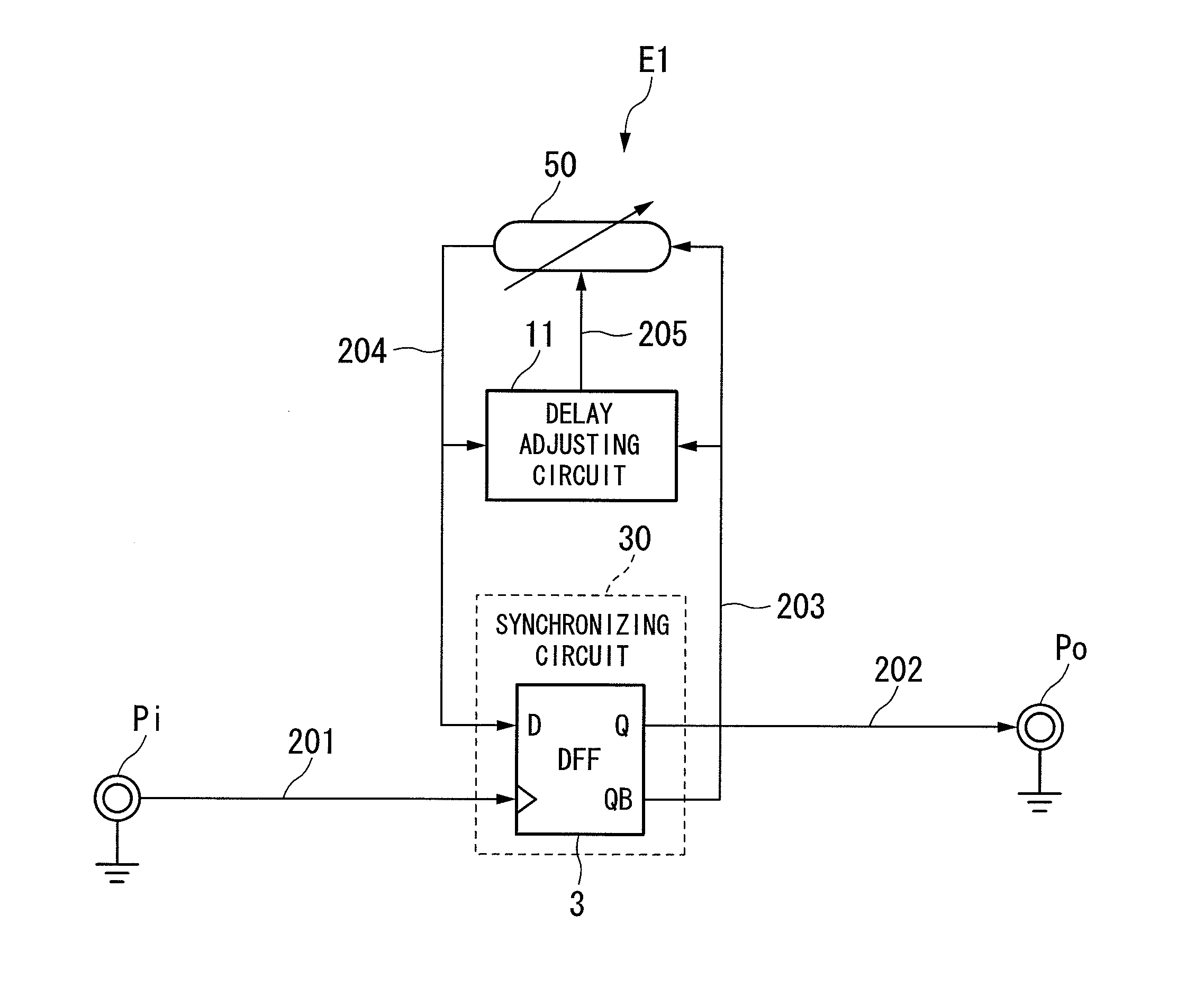
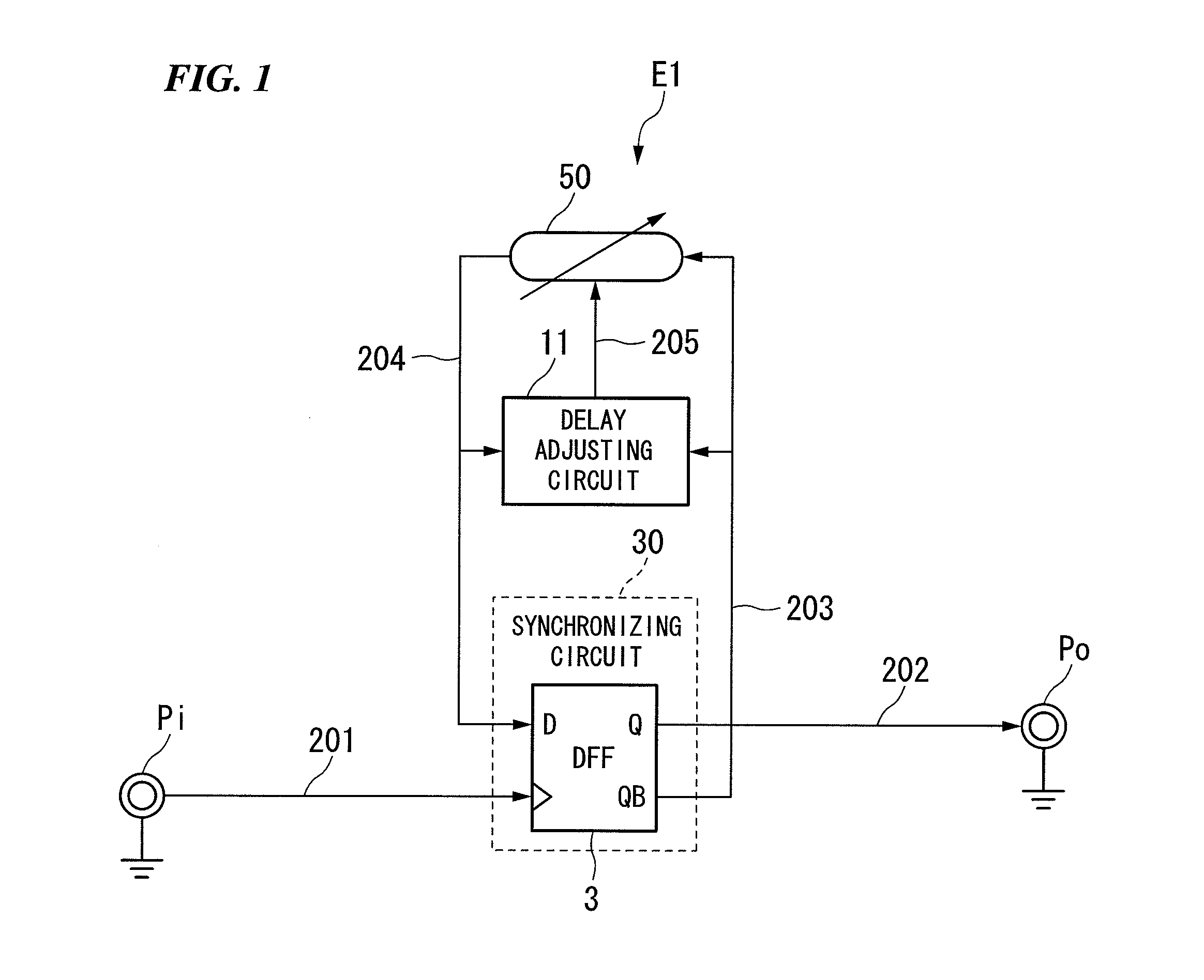
[0023]FIG. 1 shows the block diagram of the frequency dividing circuit E1 according to an embodiment of the present invention.

[0024]The frequency dividing circuit E1 shown in FIG. 1 is provided with input terminal Pi, synchronizing circuit 30, variable delay circuit 50, delay adjusting circuit 11, and output terminal Po. The input clock 201 is input to the input terminal Pi. The synchronizing circuit 30 has DFF 3. The variable delay circuit 50 variably delays signals fed back to the synchronizing circuit 30. The delay adjusting circuit 11 controls the delay time of this variable delay circuit 50. The output terminal Po outputs the frequency-divided signal 202 from the synchronizing circuit 30.

[0025]The delay adjusting circuit 11 is provid...


PUM


Abstract

A frequency dividing circuit includes: a D-type flip flop that outputs frequency-divided signal synchronized with input clock and reverse phase signal corresponding to the frequency-divided signal; a variable delay circuit that generates a delay feedback signal delayed by a specific delay time from the reverse phase signal input from the D-type flip flop and feeds back the delay feedback signal to the D-type flip flop; and a delay adjusting circuit that detects a phase difference between the reverse phase signal input from the D-type flip flop and the delay feedback signal input from the variable delay circuit, obtains detected results, and outputs to the variable delay circuit a control signal to perform control so that the delay time becomes time required to ensure setup / hold time of the D-type flip flop, based on the detected results.

Description

BACKGROUND OF THE INVENTION[0001]1. Field of the Invention[0002]The present invention relates to a frequency dividing circuit, and in particular, relates to a frequency dividing circuit suitable for high speed operations.[0003]Priority is claimed on Japanese Patent Application No. 2006-317022, filed Nov. 24, 2006, the content of which is incorporated herein by reference.[0004]2. Description of Related Art[0005]FIG. 4 is a block diagram of the conventional frequency dividing circuit E′. In FIG. 4, output from the Q terminal of a D-type flip flop (hereafter referred to as “DFF”) 3′ is fed back to the D input terminal through a variable delay element 1 and an OR gate 2. The delay time at this variable delay element 1 is controlled by the control signal 101. The output of AND gate 6 is input to the other input terminal of the OR gate 2. The output of this AND gate 6 is the logical product of the Q output of DFF 4 and a signal that is the QB output of DFF 4 delayed by the delay element 5...

Claims


Application Information

Patent Timeline
Patent Type & Authority Applications(United States)
IPC IPC(8): H03K21/00
CPCH03K23/662
Inventor FURUKAWA, OSAMU
Owner YOKOGAWA ELECTRIC CORP
Why Eureka
Try Eureka