

Direction-of-arrival estimating device and program
- Summary
- Abstract
- Description
- Claims
- Application Information
AI Technical Summary
Benefits of technology
Problems solved by technology
Method used
Image

Examples
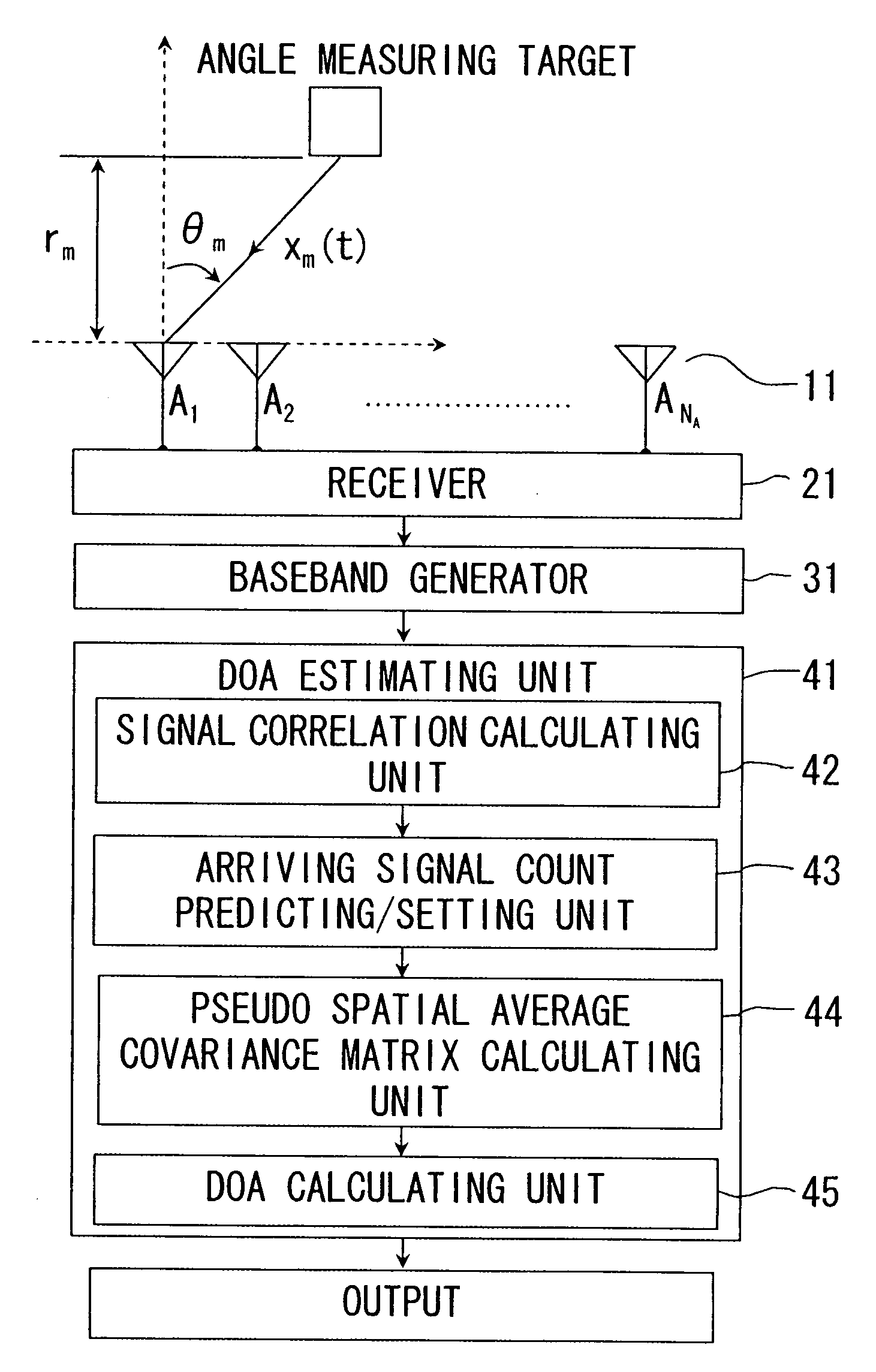
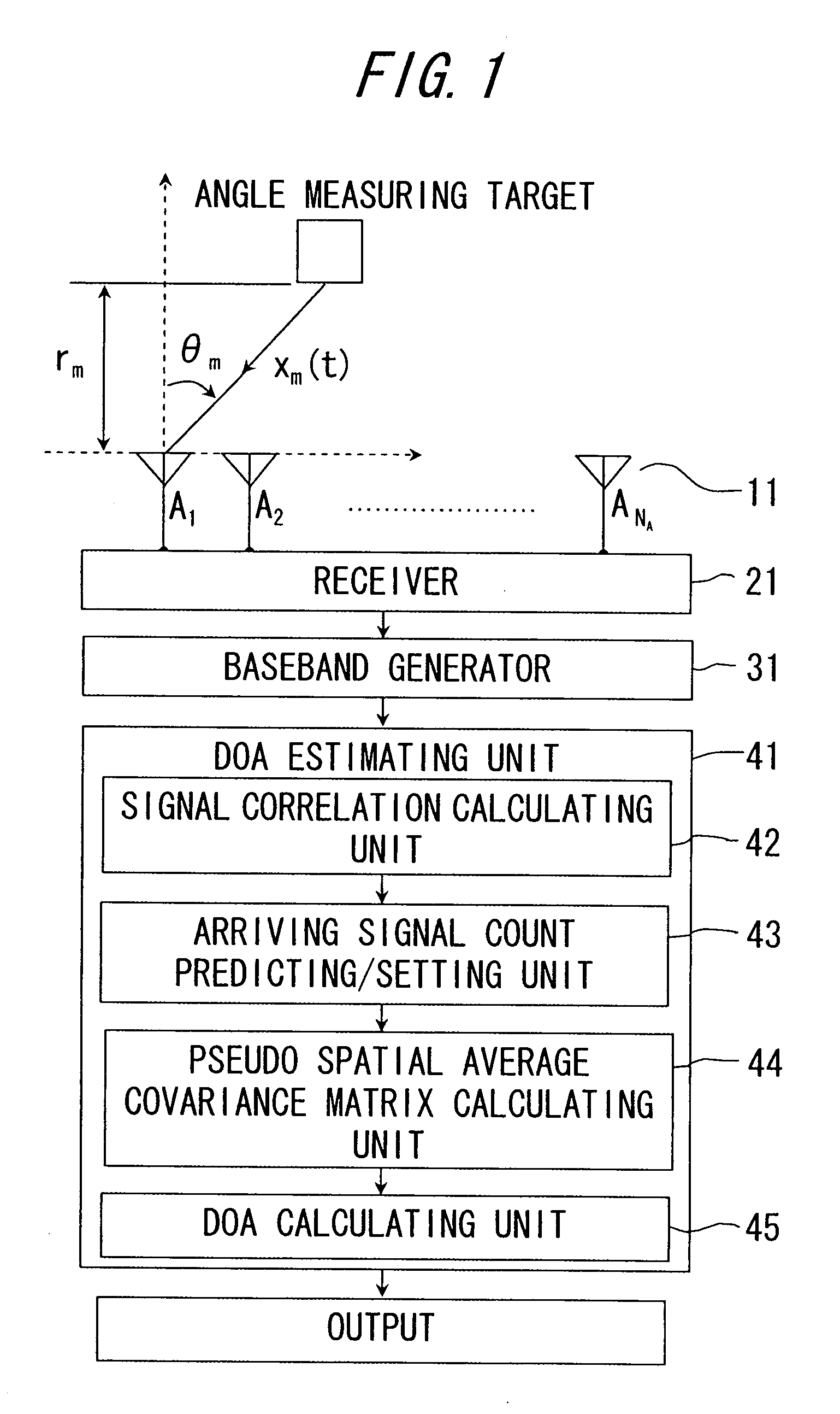
first embodiment
Modified Example of First Embodiment
[0067]In the first embodiment of the present invention, the DOA calculating unit 45 obtains (RRH)−1 when estimating the direction of arrival. In the formula (2.6) in a second embodiment which will hereafter be described, however, QS−1QH is obtained by subtracting a first term of the right side of the formula (2.6) from (RRH)−1, and hence the DOA calculating unit 45 in the first embodiment may, when estimating the direction of arrival, use a value obtained by subtracting the first term of the right side of the formula (2.6) from (RRH)−1 (which corresponds to a first submatrix forming unit according to the present invention). In this case, a submatrix R1 of NS×4NS of the matrix R acquired by the pseudo spatial average covariance matrix calculating unit 44, is obtained, and the first term of the formula (2.6) may be obtained from this submatrix R1. This operation enables the execution of the DOA estimation with higher accuracy than by the estimation ...
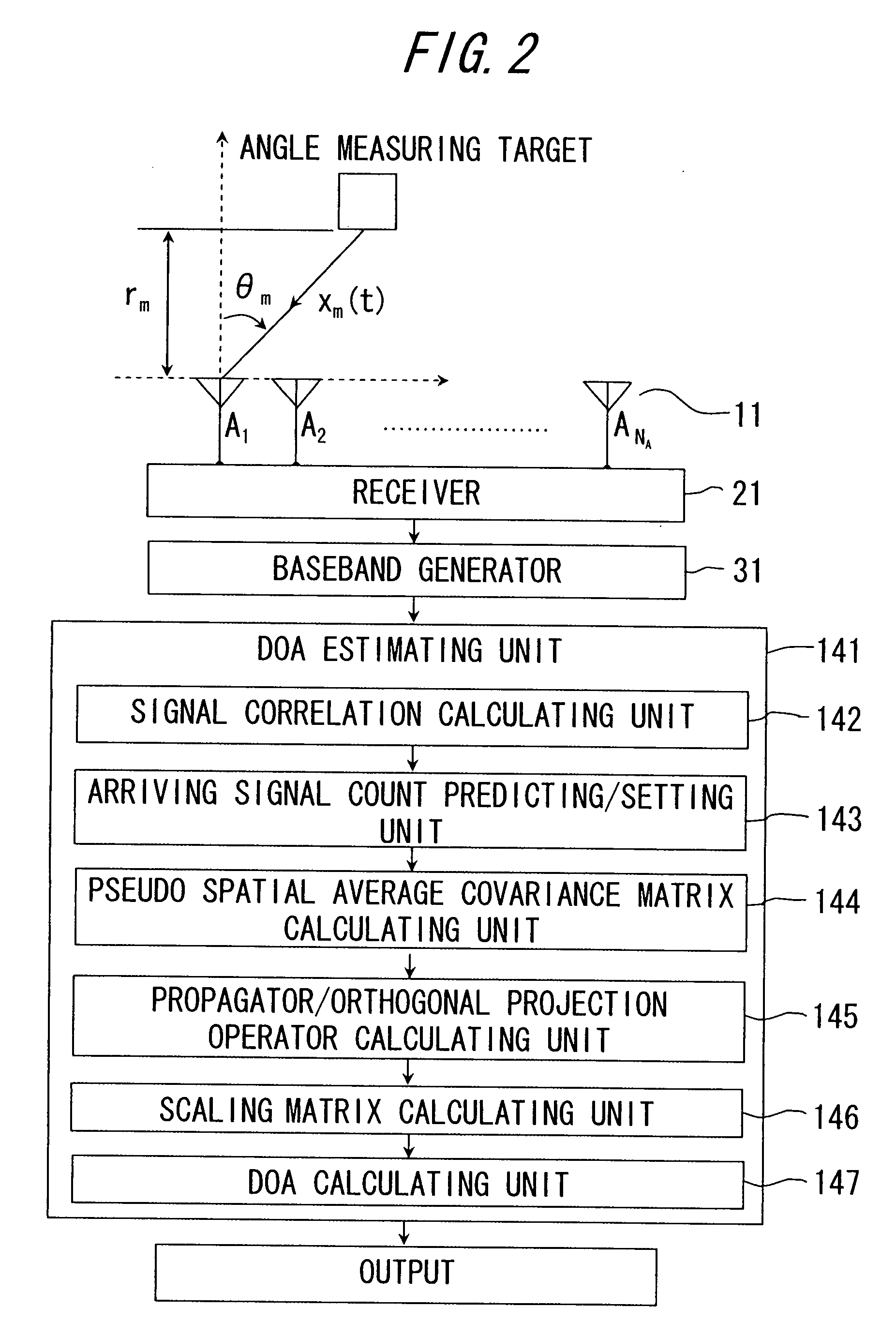
second embodiment
Operational Effect in Modified Example of Second Embodiment
[0098]When the DOA calculating unit 147 estimates the direction of arrival, the matrix calculation count can be reduced depending on how the combination is made by use of the formulae (3.1), (3.2) and (3.3), to which degree the processes required for the DOA estimation can be decreased. Hence, the DOA estimation device in the modified example can implement the DOA estimation at a high speed. Particularly in the case of employing the formula (3.2), the calculation can be attained only by a product of the two matrixes, and therefore the higher DOA estimation can be actualized. Moreover, in the case of using the formula (3.3), performance of the DOA estimation can be adjusted corresponding to the environment such as the measuring target and the weather by changing the predetermined value θ, and hence such an advantage is yielded that the flexible device can be actualized.
modified examples of first embodiment and second embodiment
[0099]The first embodiment and the second embodiment use, as the components of the DOA estimation device, the signal correlation calculating unit 42 (142) and the arriving signal count predicting / setting unit 43 (143) for predicting the arriving wave count Ns, however, the arriving wave count Ns may be set as a predetermined fixed value. Furthermore, the arriving wave count Ns may be estimated using a characteristic value derived from matrix R.
[0100]The DOA estimation method using the DOA estimating unit 41 (141), though having theoretically an eigenspace-method-wise aspect, is also considered to be the DBF using RRH in place of RvvFBSS in a formal sense. Accordingly, if construed in terms of the latter point of view, the value of Ns has a significance in only one point of forming the optimum spatial average matrix, and hence, for example, the arriving wave count Ns may also be fixed to a maximum measuring angle target count detectable by use of the matrix R obtained by pseudo-spati...
PUM
 Abstract
Description
Claims
Application Information