Imaging Optical System

Inactive Publication Date: 2008-05-29
MITSUBISHI ELECTRIC CORP
View PDF4 Cites 20 Cited by
  • Summary
  • Abstract
  • Description
  • Claims
  • Application Information

AI Technical Summary

Benefits of technology

[0017]According to the present invention, it is possible to reduce an overall size of an optical system by decreasing interva

Problems solved by technology

Further, a material is limited to an expensive material depending on a specific wavelength range such as ultraviolet rays or infrared rays, which leads to a

Method used


Image

  • Imaging Optical System
  • Imaging Optical System
  • Imaging Optical System

Examples


first embodiment

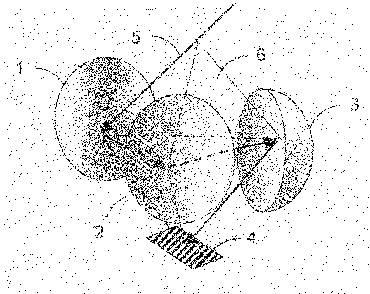
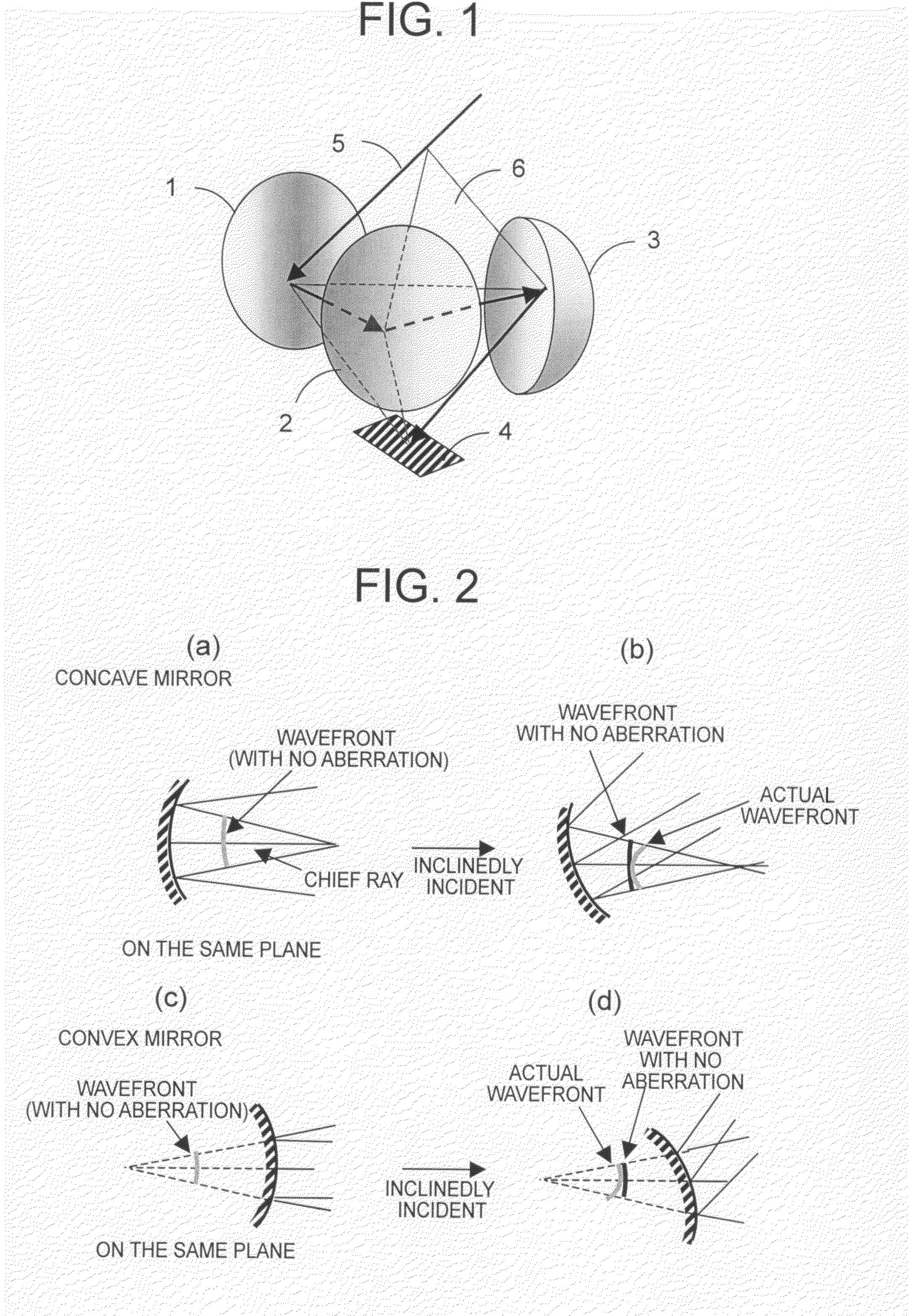
[0031]FIG. 1 is a schematic diagram showing an imaging optical system according to a first embodiment of the present invention. As shown in FIG. 1, light beams propagated from a subject are first incident to a first reflector 1 in the optical system and the light beams reflected by the first reflector 1 are next incident to a second reflector 2. The light beams reflected by the second reflector 2 are then incident to a third reflector 3 and the light beams reflected by the third reflector 3 form an image of the subject on an image plane 4. Note that reference numeral 5 denotes an optical path of a central chief ray indicating a chief ray of the light beams forming the image at the center of the image plane 4.

[0032]The first embodiment is set so that five points, i.e., an appropriate point on the central chief ray 5 incident to the first reflector 1, reflection points of the central chief ray 5 on the first reflector 1, the second reflector 2, and the third reflector 3, and an image ...

second embodiment

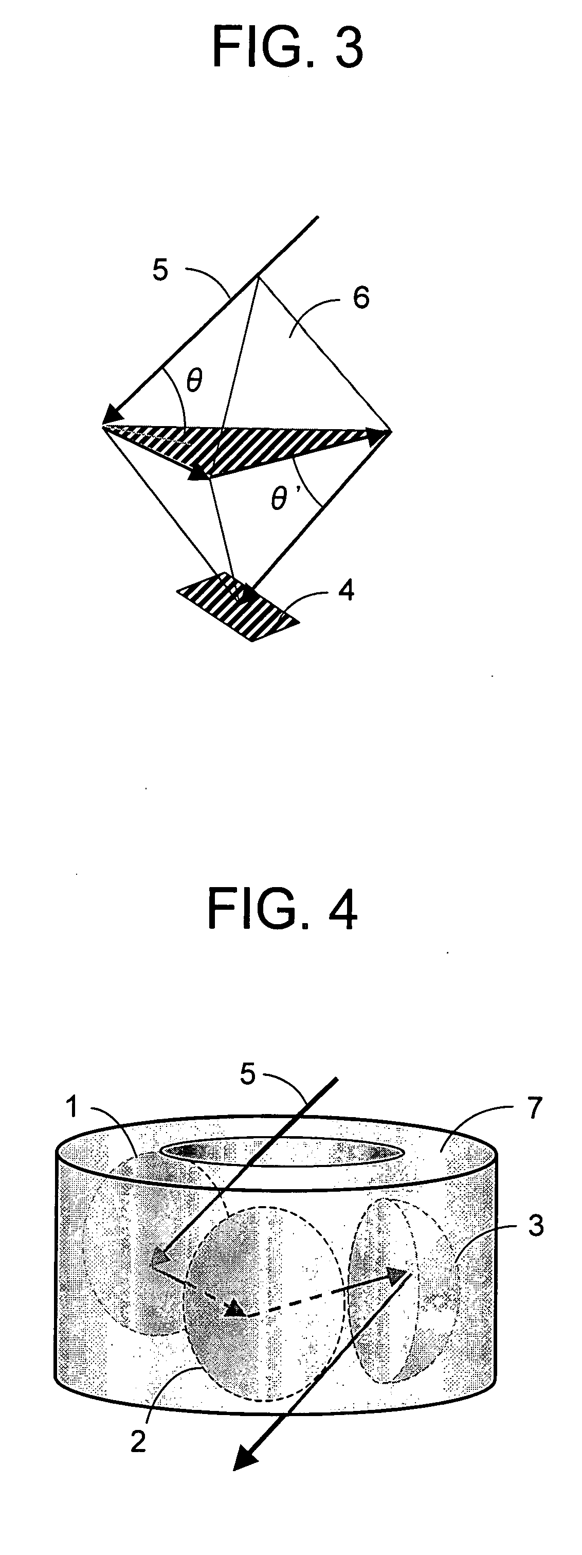
[0054]FIG. 4 is a schematic diagram showing an imaging optical system according to a second embodiment of the present invention. In FIG. 4, each portion that is the same as or the equivalent to a portion of the imaging optical system of the first embodiment shown in FIG. 1 is given the same reference numeral and a description, thereof will be omitted. New reference numeral 7 denotes an image formation member that is an integral component including structures of the first reflector 1, the second reflector 2, and the third reflector 3.

[0055]In the second embodiment, it is possible to design a compact optical system while suppressing blurring of an image by using the first reflector 1, the second reflector 2, and the third reflector 3 as in the first embodiment. In addition, in the second embodiment, all reflectors are integrated into the image formation member 7, so it is not necessary to align each reflector at the time of working, and work such as attachment and adjustment is unnece...

third embodiment

[0064]FIG. 5 is a schematic diagram showing an imaging optical system according to a third embodiment of the present invention. In FIG. 5, each portion that is the same as or the equivalent to a portion of the imaging optical system of the first embodiment shown in FIG. 1 is given the same reference numeral and a description thereof will be omitted. New reference numeral 8 denotes a relay lens that forms an image formed by the third reflector 3 on the image plane 4 again and new reference numeral 9 denotes a field diaphragm disposed at a position at which the image is formed by the third reflector 3.

[0065]In the third embodiment, the relay lens 8 and the field diaphragm 9 are provided, thereby making it possible to block stray light that is incident from the outside of a field of view, which makes it possible to obtain a high-contrast image. When light beams (stray light) other than light beams that are reflected by the first reflection surface 1, the second reflection surface 2, an...


PUM


Abstract

Provided is a compact and bright imaging optical system having a high resolution. The imaging optical system includes three reflectors composed of a first reflector (1), a second reflector (2), and a third reflector (3) that are arranged in this order on an optical path of incident ray so as not to block the incident light. In the imaging optical system, in which light beams reflected by the three reflectors form an image plane (4), a convex mirror is used for any one of the first reflector (1) and the third reflector (3) and a concave mirror is used for the other thereof, and vertexes of a triangular dipyramid (6) are defined in terms of a central chief ray (5) by an appropriate point on the central chief ray (5) that is incident to the first reflection surface, a reflection point of each central chief ray on the first to third reflection surfaces, and an image forming point of the central chief ray. A plane containing three reflection points of the central chief ray on the first to third reflection surfaces coincides with a bonding plane between two triangular pyramids forming the triangular dipyramid (6).

Description

TECHNICAL FIELD[0001]The present invention relates to an optical system that uses reflectors and is usable across a wide wavelength range, and more particularly, to an imaging optical system that is most suitable for use in an image capture apparatus, such as a camera, which takes an image of a subject.BACKGROUND ART[0002]A function required for an optical system used in an image capture apparatus is a function of gathering light incident from a subject by bending the light to thereby form an image of the subject on an image plane. Examples of an optical element having such an action of bending light include a lens that bends light by utilizing a difference in refractive indexes and a reflector that bends light through reflection.[0003]As for the lens, light passes through an inside thereof, so it is required to use a material having sufficiently large transmittance with respect to a desired wavelength range. Further, a material is limited to an expensive material depending on a spe...

Claims


Application Information

Patent Timeline
IPC IPC(8): G02B5/10
CPCG02B17/0626
Inventor NAKANO, TAKAYUKITAMAGAWA, YASUHISA
Owner MITSUBISHI ELECTRIC CORP
Why Eureka
Try Eureka