[0011]The present invention been devised in order to address this problem and it is an object therein to provide a roller drive control method for a fixing apparatus aimed at reducing adhered toner that escapes past a cleaning member by varying a
rotation velocity of a heat roller and a pressure roller between a rotation velocity of a time of a fixing process step (when a recording paper is passing through a nip region) and of a time other than the fixing process step (when a recording paper is not passing through the nip region), and aimed at improving the cleaning efficiency of a cleaning unit for adhered toner.
[0013]That is, a rotation velocity of the heat roller is set to a
low speed in the toner removal period. To describe this more specifically, a
peripheral rotation velocity of the heat roller in the fixing process period is a slightly faster velocity than a print
processing velocity of an image forming apparatus (namely, 1.005 to 1.03 times faster than the printing process speed), and a
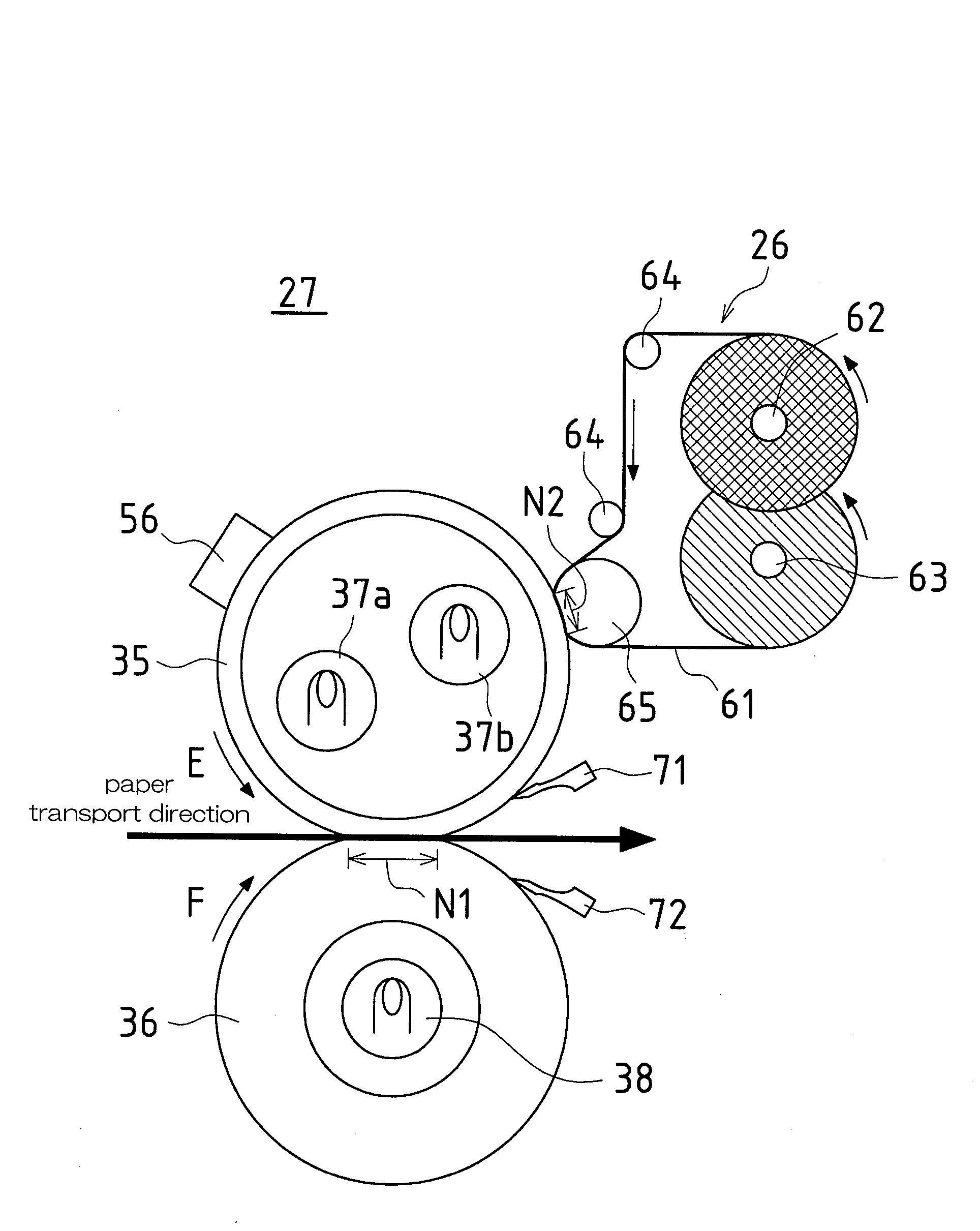
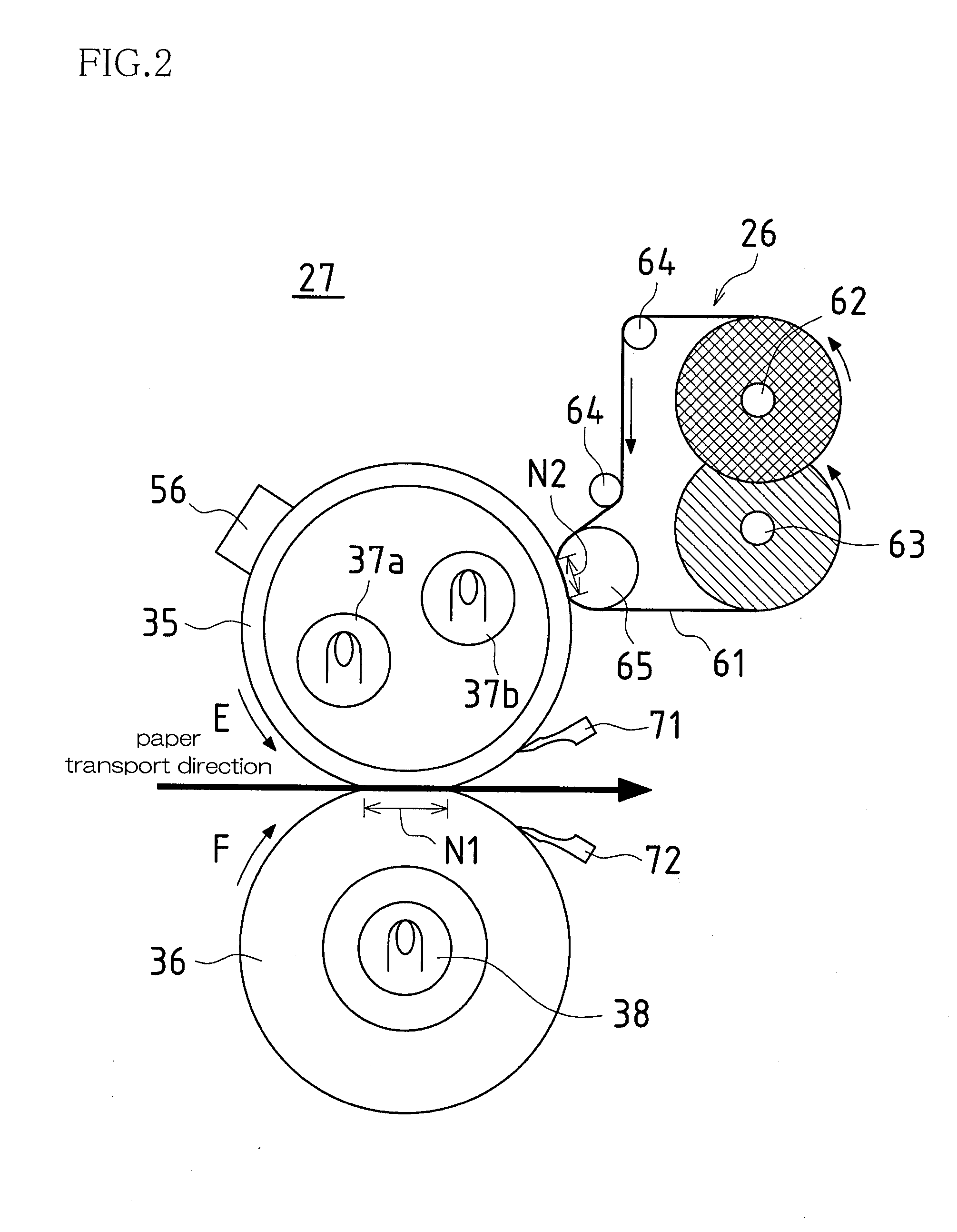
peripheral rotation velocity of the heat roller in the toner removal period is a peripheral rotation velocity 1 / 19 to 1 / 10 times the peripheral velocity of the heat roller in the fixing process period. Here, a peripheral rotation velocity of 1 / 19 is a velocity of 28 mm / sec, and a peripheral rotation velocity of 1 / 10 is a velocity of 54 mm / sec. By setting the velocity in this manner, a longer period is achieved in which the cleaning member and the smeared portions on the heat roller are in contact, thereby enabling improved cleaning efficiency for toner that has adhered onto the heat roller. Thus, when the toner that is in a melted state adhering onto the separation claw is moved in reverse to the heat roller and is transported, it becomes possible to clean the toner that has moved in reverse from the separation claw. In this way, other components arranged in areas around the heat roller (such as the detection sensors for detecting the surface temperature of the heat roller, external heating devices, and the pressure roller and the like) can be kept from becoming smeared, thereby achieving improved fixing quality. It should be noted that it is possible to use a web sheet as the cleaning unit.
[0014]Furthermore, since a longer time can be achieved for contact between the cleaning member web sheet and the heat roller when the rotation velocity of the heat roller is made
low speed, the pressing force (
contact pressure) of the web sheet pressing onto the heat roller can be reduced, thereby achieving simplification in mechanical terms and also enabling reductions in abrasions that occur on the heat roller surface. Scratches to the surface of the heat roller occur when adhered residual toner at the
contact region to the web sheet hardens when power to the fixing apparatus is stopped, and the hardened adhered toner rubs against the surface of the heat roller with a
contact pressure when power is turned on again and rotationally driving of the heat roller recommences. Further still, since the
contact pressure can be reduced, the web sheet used as the cleaning member does not deform at the contract region and does not suffer wrinkling or tearing or the like. In this way, a more stable cleaning capability can be achieved.
[0015]Furthermore, the toner removal period is set to a period in which the heat roller performs at least two rotations or more. That is, performing two rotations involves passing the pressing area at the cleaning unit two times, and residual toner that could not be fully removed the first time can be removed the second time. In this way, residual toner can be removed more reliably.
[0019]By using timing such as these, it is possible to set the toner removal period without exerting an influence on the fixing process period.
[0021]Furthermore, rotation velocity control of the heat roller is controlled by a magnitude of power given to a rotational drive source or by increasing / decreasing a number of pulses of power. That is,
rotation control for high speed rotation [(print
processing speed)×(1.005 to 1.03)] and
low speed rotation is controlled by varying the input
voltage to the rotational drive sources (
DC motor, pulse motor) and varying the number of pulses, and therefore a mechanical structure for varying speed (such as a
clutch, or a separate
gear train for driving or the like) becomes unnecessary. For this reason, it is possible to achieve simplification of control, greater compactness of the fixing apparatus, and simplification of peripheral control including control portions.

