Antenna System For Monitoring Of A Target Area

a target area and antenna system technology, applied in the field of antenna systems, can solve the problems of increasing the risk of side effects, and achieve the effect of reducing the amount of reflection and low attenuation

Inactive Publication Date: 2008-05-29
MICROPOS MEDICAL
View PDF18 Cites 12 Cited by
  • Summary
  • Abstract
  • Description
  • Claims
  • Application Information

AI Technical Summary

Benefits of technology

[0019]Further, the interface device is substantially conformable for adaptation of a shape essentially following a surface of said boundary surface of said living body. Accordingly, conditions with a close contact between said boundary surface and the interface device may be provided for a boundary that reduces the amount of reflections along the communication channel. Hence, a communication channel with a relatively low attenuation may be established between the first and second antenna device.
[0020]Advantageously, said interface device is adapted to be filled up with or drained from a medium for adaptation of its shape. The opportunity for variation of the shape of the interface device may be an advantage in medical applications where the patient with a substantially wide range of different body sizes may be treated. Preferably, the medium enclosed within the interface device having a relative permittivity closer to the permittivity of tissues within the living body than the permittivity of air.

Problems solved by technology

This requirement may cause that the healthy organs around the target will be affected by high energy radiation, thus increasing the risk for side effects as a result.

Method used


Image

  • Antenna System For Monitoring Of A Target Area
  • Antenna System For Monitoring Of A Target Area
  • Antenna System For Monitoring Of A Target Area

Examples


Embodiment Construction

[0046]Embodiments of an antenna system 1 will now be described in more detail with reference to FIGS. 1-4.

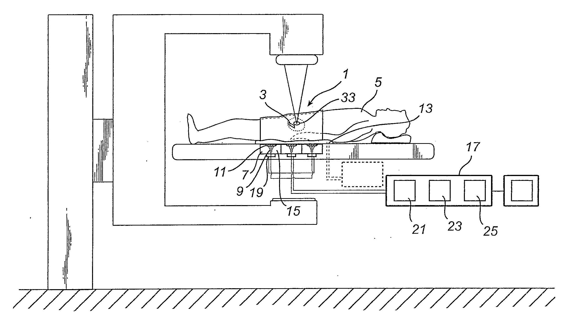
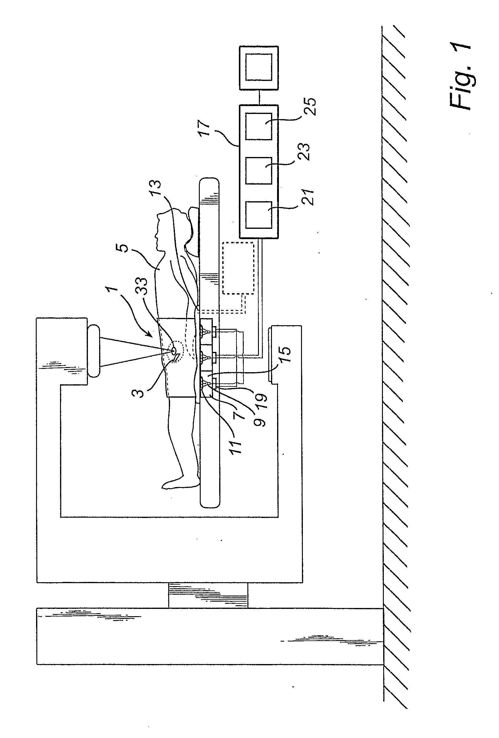
[0047]According to FIG. 1, an antenna system 1 for communication with at least one medical implant 3 located within a living body 5 is shown. The antenna system 1 comprises an antenna array 7 with a plurality of positions for measurement, preferably provided as helical antennas 9, dome devices 11 and at least one interface device 13. The antenna array 7 is composed by a plurality of antenna scanning cells 15, wherein the antenna device 9 of each antenna scanning cell 15 may be moved over the surface of said dome device 11 and thereby changing the rotational arc for alignment of each antenna device 9 towards the medical implant 3.

[0048]Additionally, the antenna system 1 according to FIG. 1 comprises an antenna system control unit 17. Preferably, each antenna scanning cell 15 has a cell scanning control unit 19 that determine at which solid angle a beam of a RF (Radio Frequency) s...


PUM


Abstract

The present invention relates to an antenna system (1, 101, 201, 301, 401, 501) for tracking of a position of a target area (33, 133, 233, 333, 433, 533) within a body (5, 105, 205, 305, 405, 505), comprising a first antenna device (3, 103, 203, 303, 403, 503) and a second antenna device (9, 109, 209, 309, 409, 509), at least said second antenna device (9, 109, 209, 309, 409, 509) is to be located outside said body (5, 105, 205, 305, 405, 505), wherein an interface region (13, 113, 213, 313, 413, 513) between said body (5, 105, 205, 305, 405, 505) and at least said second antenna device (9, 109, 209, 309, 409, 509) at least partially consist of a dielectric medium having a relative permittivity closer to the permittivity of material within the body (5, 105, 205, 305, 405, 505) than the permittivity of air.

Description

TECHNICAL FIELD OF INVENTION[0001]The present invention relates to an antenna system for tracking of a position of a target area within a living body, comprising a first antenna device to be located within said living body and a second antenna device to be located outside said living body.BACKGROUND OF THE INVENTION[0002]Patients with e.g. cancer tumors are often treated with radiotherapy, usually delivered as a plurality of fractions over a period of time. The plurality of fractions that are used for the treatment serves to reduce the risk of side effects that may be caused by the treatment.[0003]Due to organ and patient motions during the treatment, as well as between the treatments, resulting from respiration, blood flow, gastric motions, and other causes, it is often required to add a specific margin around the target area in which the radiotherapy energy should be projected, in order to keep a good treatment efficiency. This requirement may cause that the healthy organs around ...

Claims


Application Information

Patent Timeline
Patent Type & Authority Applications(United States)
IPC IPC(8): A61B5/00
CPCA61B19/52A61B19/5244A61N2005/1051A61B2019/5251A61N5/1049A61B2019/207A61B34/20A61B90/36A61B2034/2051A61B2090/101A61B5/07
Inventor ROSENGREN, BENGTLENNERNAS, BOIUSTIN, ROMANGUSTAFSSON, TOMAS
Owner MICROPOS MEDICAL
Why Eureka
Try Eureka