[0005]In the lavatory
system of the present invention many of the items associated with the operation of a hands-free wash basin, including the
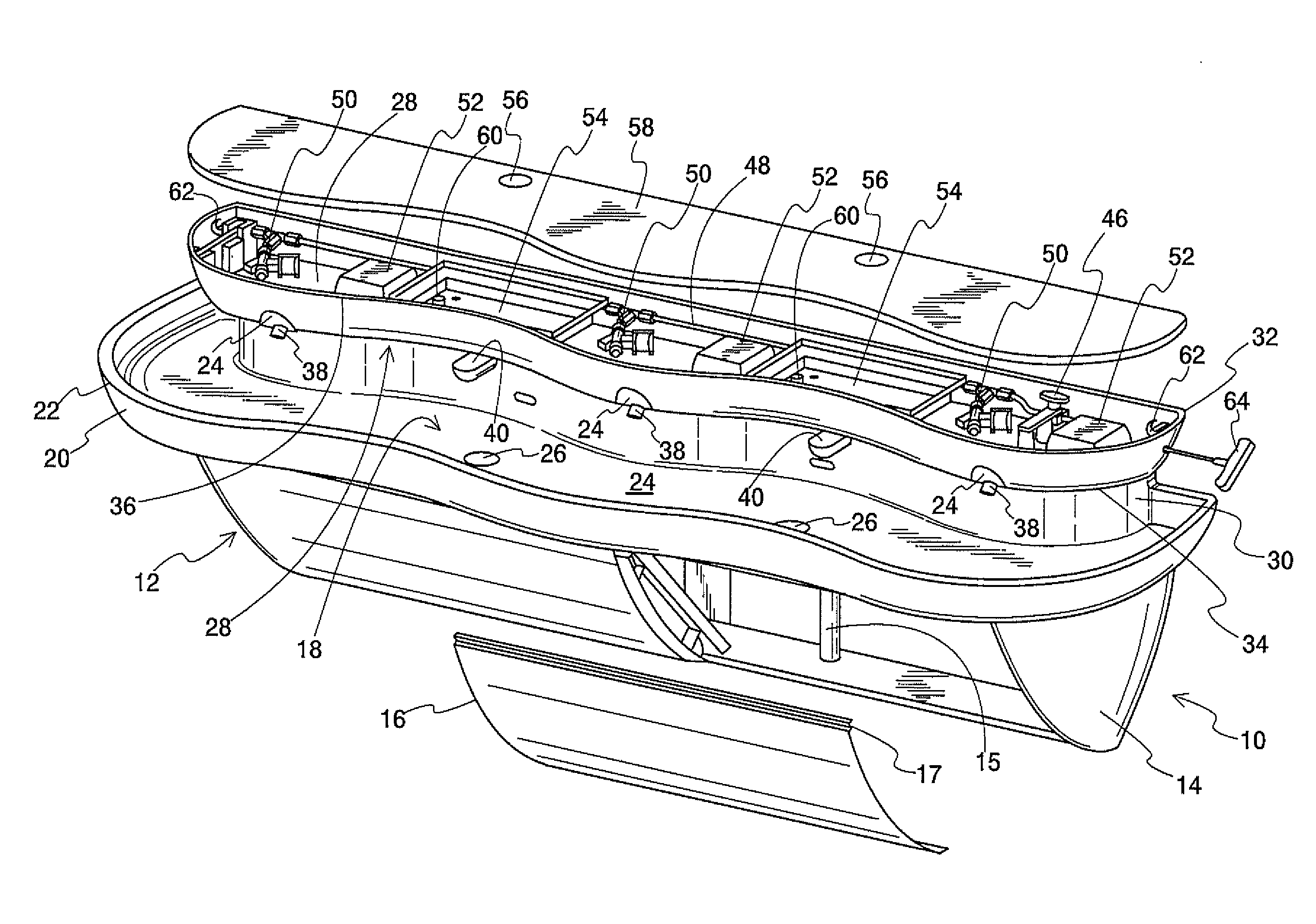
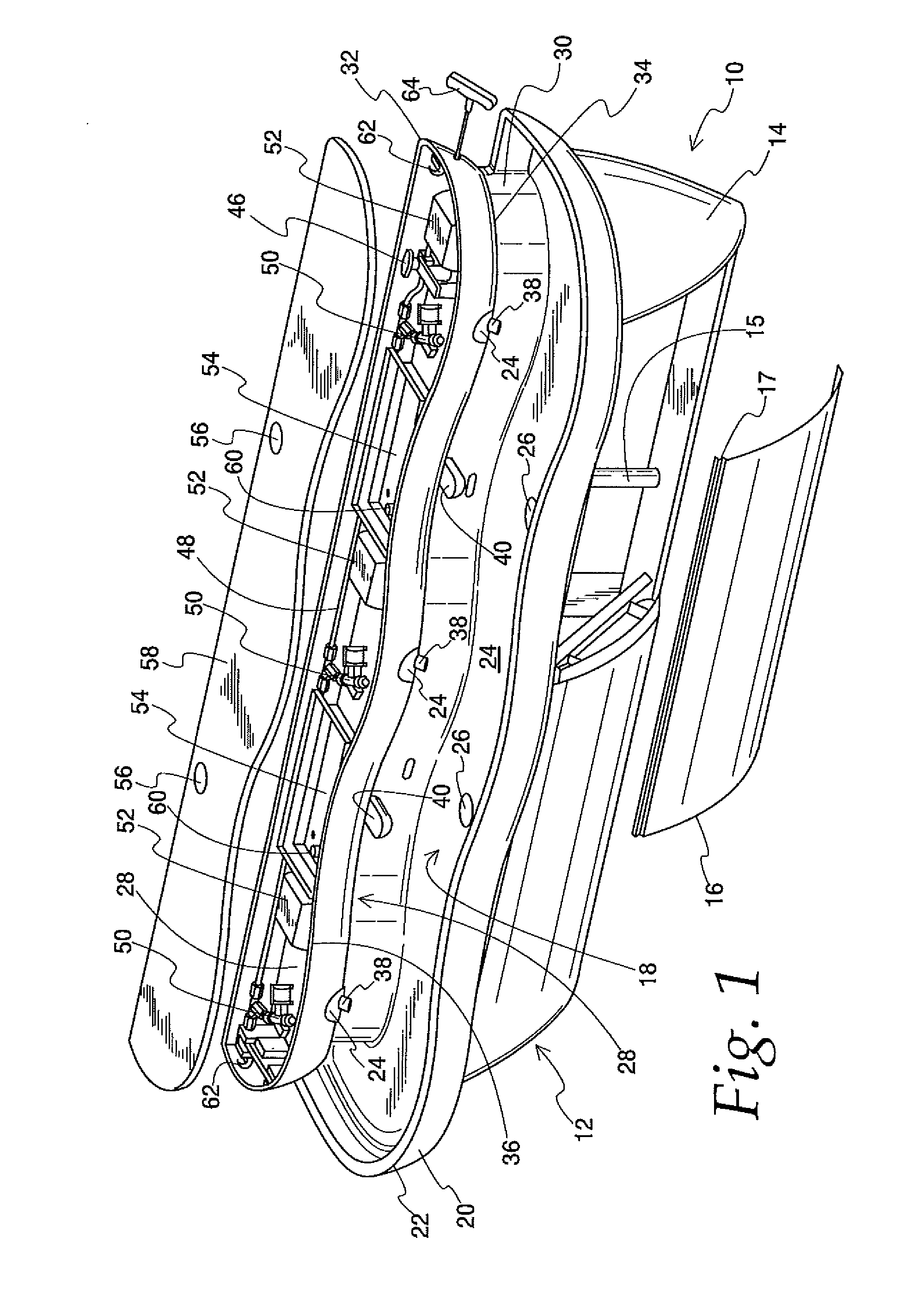
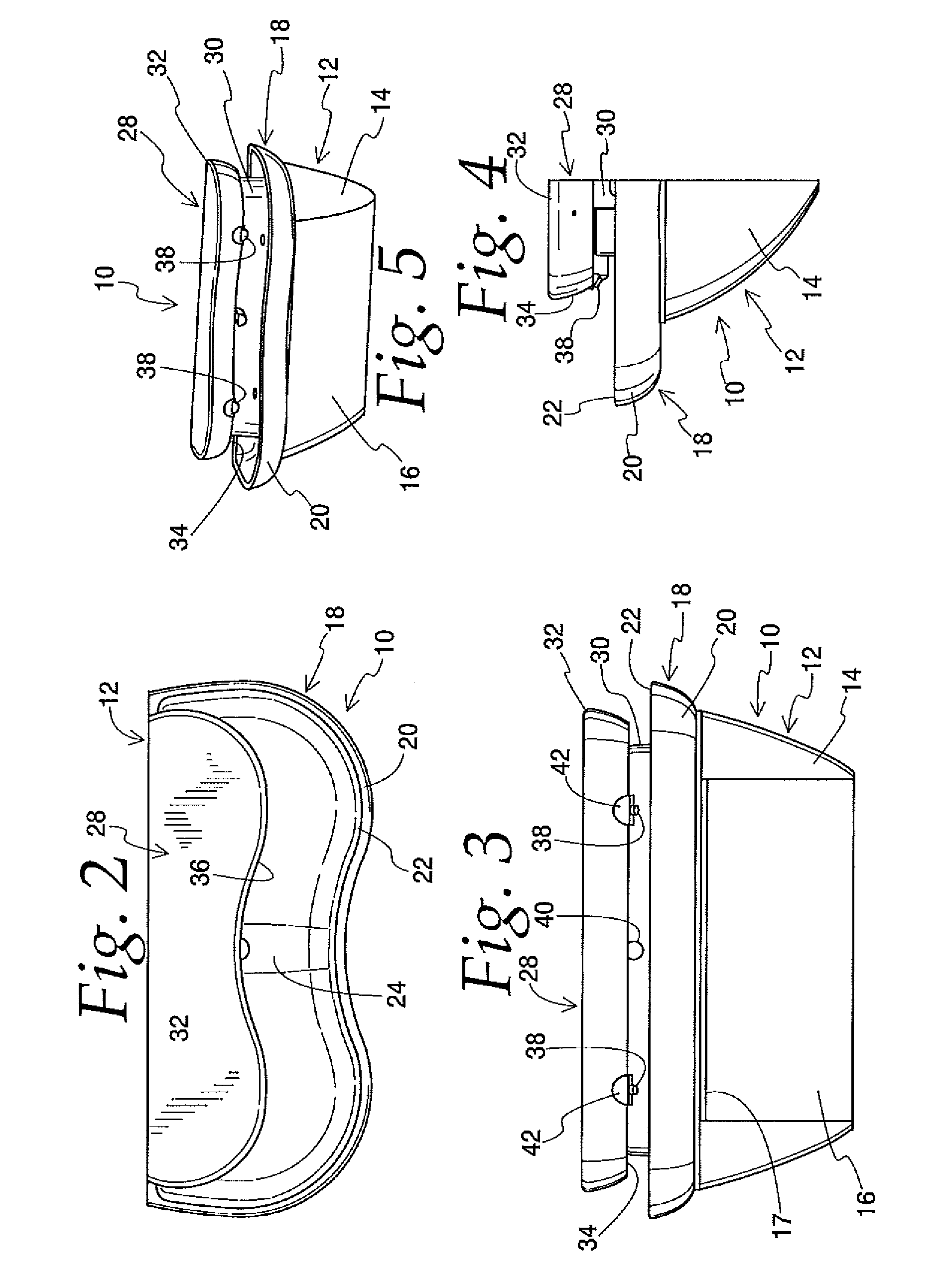
electronics and plumbing components, have been relocated from the traditional location in the base of the cabinet to an enclosed head above the basin. This design moves all
electronics (except an optional
low voltage transformer for code and safety reasons) along with the solenoid
control valves to the area directly above and adjacent the basin. This also includes adding a local shut-off feature in the head, to make servicing the plumbing components simpler. There will be no reason to access the cabinet base even to turn off the water.
[0006]Mechanical improvements in the present invention further include converting the sensing protocol from body bounce to “
on demand”, ensuring that the faucet turns on only when desired and not when someone walks past the lavatory or stops at the lavatory. This saves water and eliminates the
end user impression that the technology is not reliable. The sensor is mounted downward towards the rear of the water
stream within an insert
assembly that also houses the water outlet. The insert which mounts within the lowest elevation of the upper head
assembly, has water passage channels that allow any small liquid leaks within the head
assembly to harmlessly drain into the basin below. For the installer / contractor, the frame and housing components (basin, end caps, and
front panel) are totally disjointed in the installation process. Once the frame is installed, the housing components can be fastened to the frame. The frame rails on the frame have been designed to account for where and how the installer anchors the frame to the wall. These improvements alone permit a single individual to install the lavatory, thereby reducing the installation labor costs.
[0007]An additional improvement that benefits the installer and
service personnel is that all electronic and water control devices (e.g., solenoid valves and
ball valve shut off) have been relocated to the upper head and are supplied factory installed. This further reduces installation time as only a
single line needs to be run from the stop (which is located in the wall but still below the basin to fit standard rough-in procedures) to the upper head assembly and attached to the supplied
ball valve. Similarly, a single two-lead power wire is run from the
transformer (located below the basin) to the first circuit board in the upper head. Once powered up the faucet sensor range can easily be adjusted from the sink top. An electrical tether is used to permit more remote location of the sensors from the circuit board, which in turn facilitates
on demand activation. All electronic devices within the upper head are positioned onto standoffs molded into the upper head bottom surface making sure that any unexpected water leaks drain below the electronic components towards the insert water passage channels via a sloped
deck down into the basin. Periodic servicing of solenoids allows small amounts of water entrapped in the water passages to harmlessly flow into the basin.
[0008]This also means that when the solenoid screens need to be cleaned, the service person removes the lid and turns the water off using the
ball valve, relieves the pressure in the local
system and proceeds with the service. With the control module located in the upper head, all diagnostics are conveniently located for
troubleshooting sensor range and electronic continuity. The service person no longer has to get on his knees and remove the front access panel. If he does, however, need
front panel access for some other purpose, even that has been improved. Rather than sliding out sideways, which can be difficult in a corner, the
front panel is attached by a hanging lip at the top edge and fastened at the bottom by several hidden fasteners. This construction provides a
clean appearance, is not prone to vandalism, and is easy to remove and install. The lid attachment is achieved by using a standard latch with obscured releases.
[0009]When
soap is an option the dispenser tray is filled through an opening in the top of the lid. An overflow is included in the tray in the event that too much
soap is poured. The overflow can be easily removed for cleaning as can the entire tray by simply lifting off the supply tube. Should a
soap overflow condition occur, the upper head angling frontal towards the basin, safely drains the overflow into the sink basin, one of the benefits of having the liquids in an upper head configuration over the basin
deck. The soap
actuator is positioned for horizontal activation which is more ergonomic than vertical operation. The human interface has been significantly enlarged distributing the force load over a broad surface of the palm. The present invention has also been designed to better accommodate the requirements of the American with Disabilities Act with respect to the mounting height, recognizing the need for flexibility.


